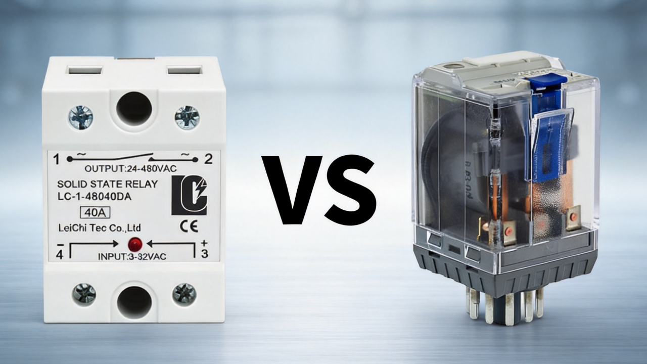
The solid state relay is a very common semiconductor component, widely used in industrial applications, but do you know exactly how it works? In this article, I’ll help you better understand the solid state relay working principle and how it works.
What is a Solid State Relay
A solid-state relay is an electronic switch that uses semiconductor components to control a circuit, providing electrical isolation between the control circuit and the power supply circuit for high-power loads whilst operating in a static manner. Features such as quiet operation, high-frequency switching and a long service life, combined with its ability to control high-current loads, mean it is frequently used in industrial automation systems, temperature control systems and power control systems.
How does a Solid State Relay Work
The working principle of a solid state relay is based on semiconductor switching. When a control signal enters the input circuit, the isolation circuit transfers the signal while separating the control side and load side; the trigger circuit processes the signal and determines the switching method; the output semiconductor device turns on or off to control current flow to the load. Unlike electromagnetic relays, SSRs complete the entire switching process electronically without mechanical movement.
To understand the entire process, one must know the internal structure of an SSR and its switching mechanism. The internal components vary depending on the SSR type, but most follow the same switching procedure and share the same internal structure.
Internal Structure of SSR
A typical solid state relay consists of five functional blocks: input circuit, isolation circuit, trigger circuit, output switching circuit, and protection circuit.
- Input Circuit
The input circuit is responsible for receiving input signals from the control devices and converting them into current inside the SSR. They typically include a current limiting resistor and a protection circuit against reverse polarity; more complex SSRs may incorporate constant-current circuits with an extended voltage range.
- Isolation Circuit
Isolation Circuit is achieved using optocouplers; control signals are typically transmitted via optical transistors, optical diodes, or bidirectional optoelectronic thyristors. It protects your PLC and drives, enhances electrical safety, and reduces electrical interference.
- Trigger circuit
The trigger circuit is used to process the received input signals, then control the switching devices, and supports multiple control modes to switch the desired output signal. It determines how and when your output switching devices are activated.
- Switching Circuit
Switching circuits control the current flowing through semiconductor devices and transfer power to the load. Due to the wide variety of output types, there are many different configurations available; among the most common are MOSFETs, IGBTs, TRIACs, and SCRs.
- Protection Circuit
Since the electronic structure of SSRs is more sensitive to electrical noise and voltage transients, they are equipped with protection circuits against overvoltage, electrical noise, and overheating. These circuits typically include MOVs, RC snubber, TVS diodes, and overheat protection.
SSR Switching Process Explained Step by Step
The solid state relay performs the entire electronic switching process without any physical contact; throughout this process, the control circuit and the load circuit remain electrically isolated.
Step 1: Control Signal Is Applied
The control signal is applied to the SSR input; the input circuit processes this signal, limits the input current, and then transmits this current to the isolation circuit.
Step 2: The Optocoupler Transfers the Signal
The input current powers the LED inside the optocoupler; the light activates the photodetector, enabling the transmission of the control signal without direct electrical connection. This optoelectronic isolation effectively reduces the impact of high-voltage transients and electrical noise from the load side on control circuits.
Step 3: The Trigger Circuit Determines the Switching Action
The triggering circuit processes control signals and controls the activation mode of output switches; it generally includes three control modes: zero-crossing switching, random turn-on, and phase angle control.
Zero-cross Switching: It only operates when the alternating load voltage is zero or close to zero, which helps you reduce electromagnetic interference and noise.
Random Turn-on: Since it can conduct current at any time within the alternating load’s voltage range, it can easily generate more electrical noise.
Phase-angle Control: Delays conduction within each AC cycle to regulate output power.
Step 4: The Output Switching Device Conducts
The triggering circuit controls the output switching device, allowing the load current to flow. Generally, DC SSRs use MOSFETs or IGBTs, while AC SSRs use TRIACs or SCRs; the current is then directed to the load.
Step 5: The Load Operates
The switching device is activated, allowing current to flow through the load and power connected equipment such as heating elements, motors, electric water heaters, or lighting systems.
Step 6: The Control Signal Is Removed
When your control signal is removed, the trigger circuit turns off the output switching device. Current flow to the load stops, completing the switching cycle.
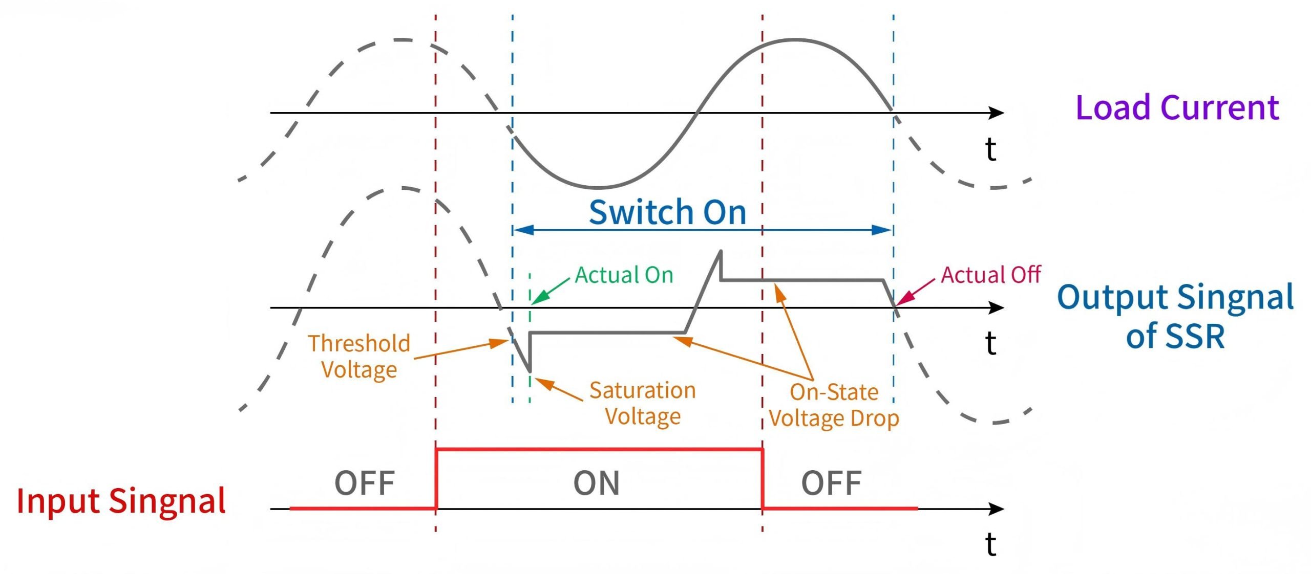
In summary, when your control signal is applied to the input of an SSR, in optically isolated SSRs, the input signal drives the internal LED of the optocoupler, then activates the switching component at the output level. You will find that when the control signal arrives at the input, the output switches to the “ON” state; when the control signal ceases, the output switches to the “OFF” state.
Advantages and Limitations of Solid State Relays
Solid state relays use semiconductor switches instead of mechanical contacts. This electronic switching mechanism offers advantages such as fast switching, long service life, quiet operation, and high reliability, making them ideal for a wide range of industrial applications.
However, semiconductor structures also have limitations, such as heat generation, leakage current, and sensitivity to overvoltage.
Advantages and Applications of SSR
Solid state relays offer numerous advantages and are suitable for a wide variety of environments, making them one of the most versatile types of relays.
- Long Service Life and High Reliability
This is the fundamental advantage of solid state relays: they offer higher switching frequencies and a lifespan that can reach millions of cycles, or even more. It offer more reliable operation in high-frequency switching applications and are widely used in industrial automation, such as PLC control panels, CNC machines, High-speed Packaging Machines, Automated Sorting Systems.
- Fast Switching Speed
Solid state relays are not subject to the mechanical switching delays characteristic of electromechanical relays; they offer faster response times, typically in the millisecond range, or even microseconds, which makes them suitable for applications requiring rapid response, such as Plastic Injection Molding & Extruders, Industrial Ovens, Furnaces & Reflow Ovens.
- Silent Operation
Solid state relays operate without physical contacts and produce no mechanical noise, such as the clicking sound associated with contact engagement, making them ideal for noise-sensitive environments, particularly in building automation, laboratories, and medical equipment.
- No Contact Bounce and Stable Switching
Unlike conventional mechanical relays, solid state relays are free from contact bounce and switching arcs, providing smoother switching and more stable operation in environments subject to vibrations and shocks, such as heavy industrial equipment.
Limitations of SSR
Solid state relays also have certain limitations you are worth noting for specific applications:
- Heat Generation and Heat Dissipation
The semiconductor components of a solid state relay exhibit voltage drop in the conducting state; the current flow results in power loss and heat dissipation.
- Load Compatibility Issues
Due to the different behaviors of various loads, solid state relays cannot directly control all types of loads.
- Surge Voltage and Overcurrent Sensitivity
Key internal components of solid state relays, such as TRIACs, SCRs, and MOSFETs, are sensitive to transient overvoltages.
- Leakage Current
Even when open, a solid state relay does not experience physical separation; semiconductor components or internal protection circuits may still allow a small current to pass.
FAQ
How to Choose the Right Solid State Relay?
A suitable solid state relay enables your application to benefit from faster and more precise control, maximizing the performance of your equipment. To select an appropriate SSR, key factors such as load type, current, rated voltage, thermal dissipation issues, and switching type should be considered.
What is the Difference Between AC SSR and DC SSR?
They differ in the type of current they control and their key internal components, and also in the fields of application.
AC SSRs utilise TRIACs or SCRs as output switching elements; these components are used to control alternating current and automatically switch off at the zero-crossing point of the AC signal.
DC SSRs typically use MOSFETs or IGBTs to control direct current; as direct current does not naturally pass through zero, semiconductor devices are required to actively interrupt the current.
How to Connect Solid State Relay?
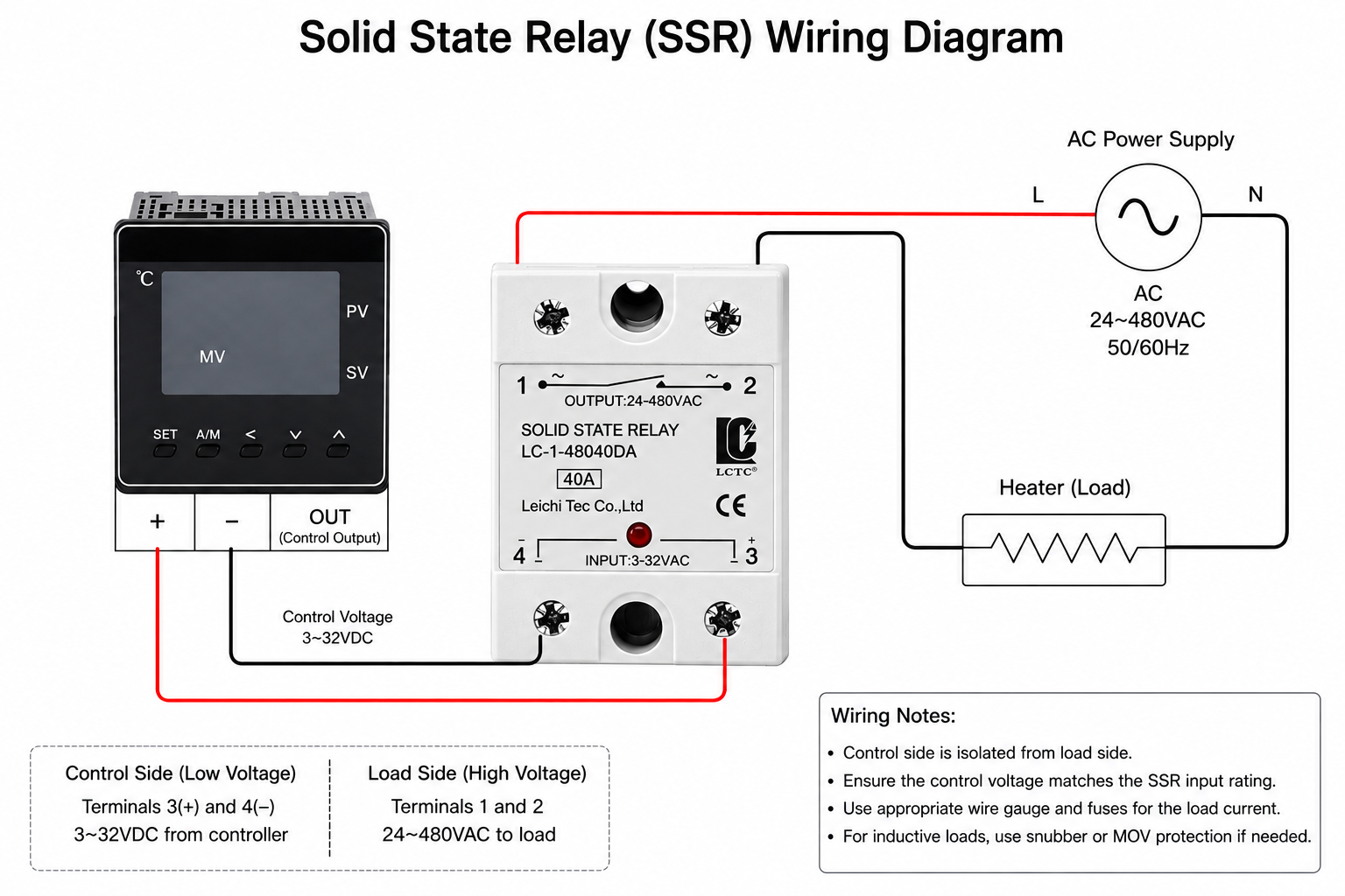
You can wire the input of the solid state relay to the controller, then link its output in series with the power supply and load; this is the simplest wiring configuration. When connecting, ensure that the technical specifications of the SSR match those of the load.
How to Check SSR Relay?
You can check the solid state relay by inspecting the input control signal, the output switch status, its physical condition, and the compliance of the input voltage, among other things. In case of overheating, if the relay remains conductive in the absence of an input signal or fails to switch, it may indicate that the relay is damaged.
How to Test a Solid State Relay with Multimeter?
Start by measuring the input voltage to verify it falls within the nominal range, then apply a control signal to check the proper operation of the output terminals. To do this, use a multimeter to inspect the status of the input signal and the output switches. If no control signal is present at the output to maintain conduction, or if a signal is present but conduction does not occur, this indicates that the SSR is likely faulty.
You can also test the SSR’s DC output using a diode to verify whether the optocoupler’s LED at the input is functioning properly. Apply a low voltage to the input using the “diode” function of the multimeter. If the device shows a direct voltage drop across the LED, it means the connection is correct; if it displays “OL,” it indicates that the connection is reversed.
Can a Solid State Relay Fail in the ON State?
Yes. In the event of overvoltage, electric shock current, overload, overheating, or other causes that may damage the internal components of the solid state relay and cause it to enter a permanent conducting state, the relay may remain locked in the “ON” position.
To prevent such situations, you can select an SSR with suitable rated characteristics and, if necessary, install protective components.
What Voltage and Current Ratings Are Available for Solid State Relays?
The standard DC input range is between 3-32 VDC, while the standard AC input range is between 70-280 VAC. The AC output voltage range is typically between 24-480 V AC, while the DC output voltage range is generally between 5-220 V DC. The nominal current is generally between 10-120 A.
Can a Solid State Relay Replace a Mechanical Relay?
Yes, solid state relays can replace mechanical relays in many applications. However, SSR is not suitable for all use cases; for certain applications, EMR remains more appropriate.
The specific choice will depend on the application’s particular requirements, such as load type, switching frequency, thermal dissipation needs, reliability requirements, and cost, among others.
How do I Choose the Right Heat Sink for a Solid State Relay?
To select an appropriate heat sink, it is necessary to know the thermal power dissipated by the solid state relay and the thermal resistance of the heat sink.
For short-term operation and low-intensity environments, select a small heat sink; for continuous operation and high-current environments, choose a larger heat sink; in high-temperature environments, reduce the rated power of the SSR and use a larger heat sink.
Can I Connect Multiple Solid State Relays in Parallel to Increase Current Capacity?
In certain applications, this method can increase current capacity, but it is not easy to implement and is generally not recommended. For high-current applications, it is recommended to use an SSR with a higher rated current or to implement an appropriate parallel configuration.
Final Thoughts
The solid state relay, which uses semiconductor switches instead of mechanical contacts, provides a reliable solution for controlling electrical loads.
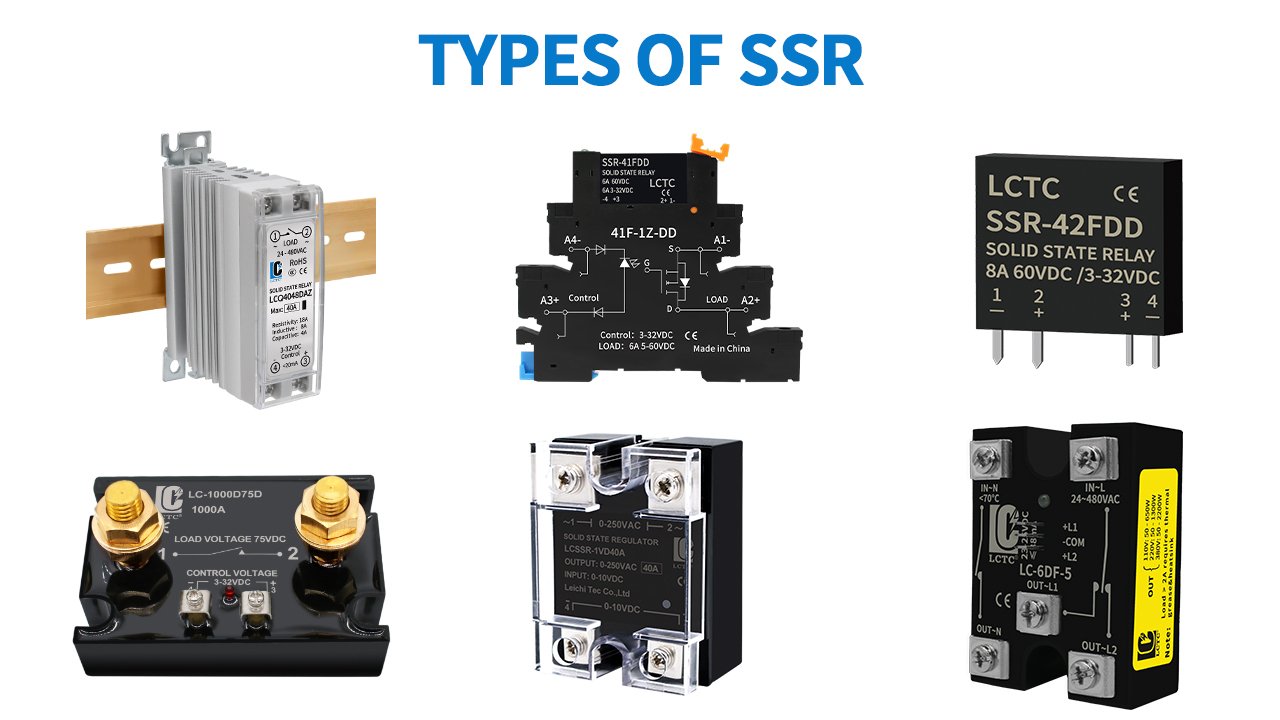
LCTC offers different types of SSRs for direct current and alternating current, both single-phase and three-phase, as well as rail-mounted models, suitable for various types of loads and installation configurations, tailored to your industrial control requirements.