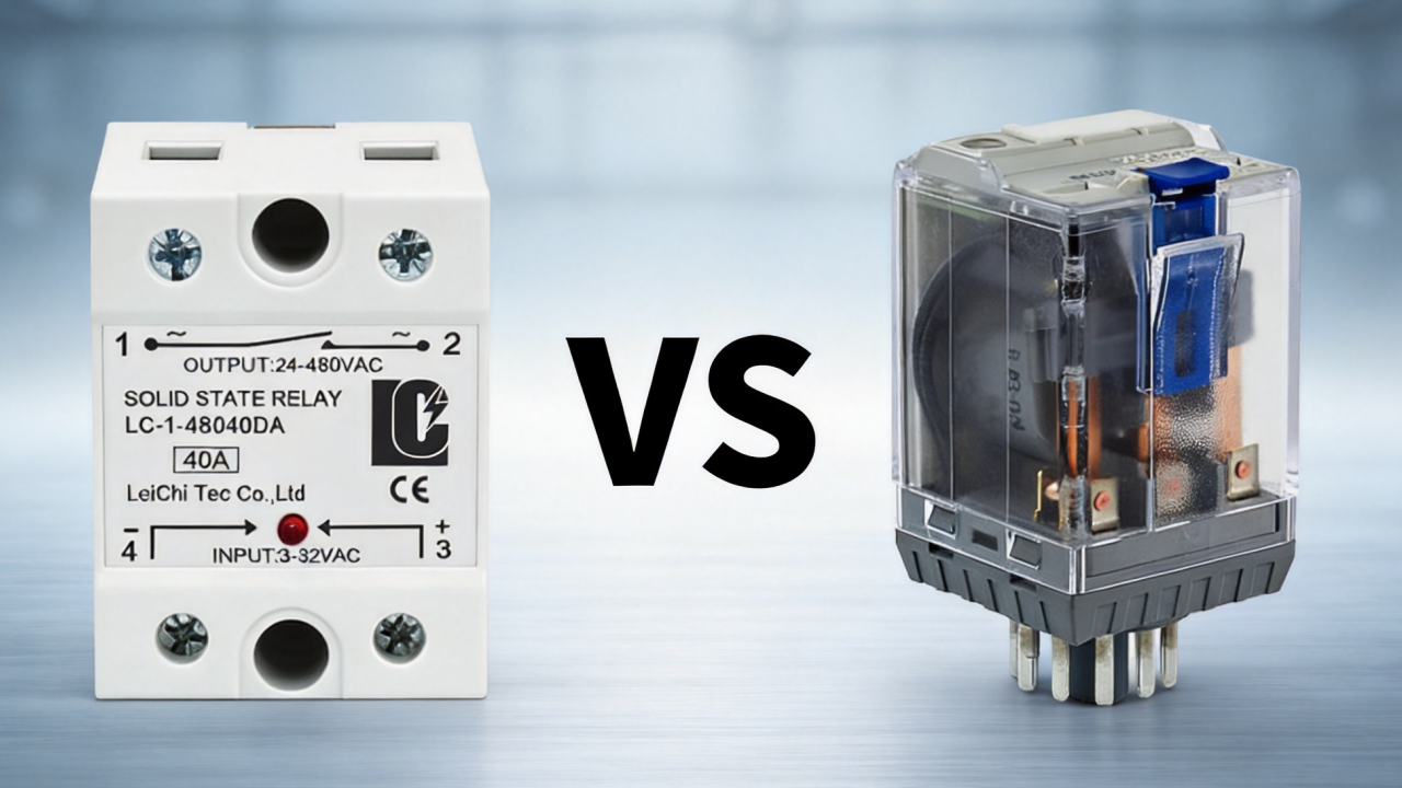
Solid state relays are electrical components widely used in industrial applications, particularly in industrial automation and temperature control systems. They can be classified into various types from different perspectives. By reading this article, you will not only gain a better understanding of SSR classification, but also learn how to select the appropriate solid state relay for your requirements.
Specific Solid State Relay Types
To meet the requirements of application environments across various industries, adapt to different loads and installation environments, etc. Solid state relays are generally classified according to five criteria: input and output type, load type, switching mode, isolation mode, and mounting method.
The various classification methods, which analyze components from different angles, help you select the SSR best suited to your specific electrical requirements and operating environment.
| Classification | Main SSR Types |
| By Load Type | AC SSR, DC SSR |
| By Input and Output | DC-DC, DC-AC, AC-DC, and AC-AC |
| By Switching Method | Zero-Cross, Random Turn-On |
| By Isolation Method | Photo Coupled, Transformer Isolated, Reed Isolated |
| By Mounting Method | DIN rail, PCB, bracket, and panel-mounted |
Since each category describes different relay characteristics, a single SSR can belong to multiple categories simultaneously. These various classification methods for analyzing SSRs from different perspectives help you select the most suitable SSR for your specific electrical requirements and operating conditions.
Types of SSR by Load Type
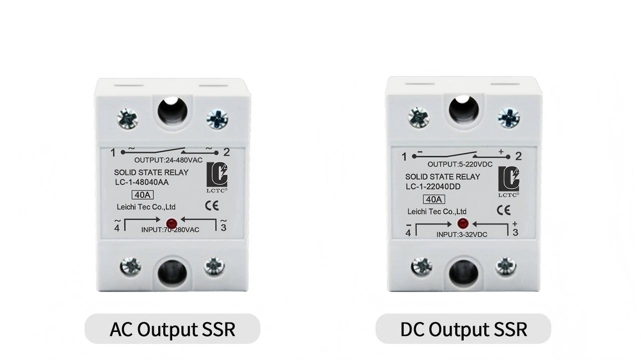
Depending on the load type, they are primarily divided into two types of solid state relays: DC SSR and AC SSR. The key difference between these two lies in the type of load.
DC SSR
Suitable only for switching DC loads, not for AC loads. MOSFETs or IGBTs are typically used as switching devices; the specific variant employed depends on requirements regarding rated voltage, rated current, and other parameters.
Common DC loads include DC motors, solenoid valves, DC heaters, electromagnetic actuators, LED loads, battery-powered devices, and DC control circuits.
AC SSR
Since it is designed for AC loads, it cannot be used for DC loads either. Because AC SSRs primarily use SCRs or TRIACs as switching devices, these components and their switching mechanisms are designed for operation in alternating current, whereas DC loads themselves do not exhibit zero-crossing characteristics.
Common AC loads include heating elements, industrial heaters, ovens, lighting, fans, AC motors, and solenoids. However, with certain inductive loads, you must also consider the issues of inrush currents and voltage spikes when using an AC SSR, and take additional protective measures if necessary.
AC SSRs are classified into single-phase SSRs and three-phase SSRs depending on the number of phases controlled.
- Single-phase AC SSRs are suitable for power supply in single-phase AC circuits, such as single-phase heating, temperature control equipment, small industrial machinery, and similar applications.
- Three-phase AC SSRs are suitable for switching multi-phase loads in three-phase systems, such as in three-phase heating, industrial heating systems, and three-phase industrial loads.
How do you determine whether an AC SSR or a DC SSR is needed? You need to verify the voltage type of the load (output side), not the type of control signal (input side); whether the input is AC or DC is irrelevant to the load type.
Types of SSR By Input/Output
Depending on the type of input and output, four basic configurations can be distinguished: DC-DC, DC-AC, AC-DC, and AC-AC.
DC to DC SSR
Using a DC control signal, the on and off of the DC load is controlled, meaning that both the input and output are DC, and the low-voltage control signal can drive individual loads. Common configurations consist of IGBTs and MOSFETs and are typically equipped with a protection diode to prevent polarity reversal.
DC to AC SSR
Using a DC control signal, the switching of an AC load is controlled, meaning DC is applied at the input while AC is output at the output. Examples of this include AC loads controlled by PLCs, temperature controllers, and similar applications, these are all common DC-AC uses.
AC to DC SSR
Using an AC control signal, the switching of a DC load is controlled, meaning alternating current is applied at the input while direct current is supplied at the output. Typically, rectifiers or other AC detection circuits are used to detect AC control signals and create electrical isolation from the DC output circuit.
AC to AC SSR:
The on and off of the AC load is controlled via an AC control signal, meaning that alternating current is present at both the input and output. The input circuit checks the AC control signal, while the isolated output circuit uses a TRIAC or SCR to switch the AC load.
When selecting the input and output configuration, you need to ensure that the SSR matches the control signal and the load voltage.
Types of SSR By Switching Method
Depending on the type of AC load switching at the output, two types can be distinguished: zero-cross SSR and random turn-on SSR.
Zero-Cross SSR
It does not turn on immediately upon receiving a signal, but operates when the load’s AC voltage is zero or nearly zero. This type of SSR generates only minor switching transients, making it particularly suitable for resistive loads such as heaters or heating elements. Zero-crossing also helps reduce electromagnetic interference and electrical noise.
Random Turn-On SSR
Upon receiving a trigger signal, the AC waveform can switch at any given time without having to wait for it to reach zero. This method allows for more precise control of the switching timing. This means that if you need to precisely control the timing of AC power on and off, or switch the load at specific points in the AC waveform, random turn-on is a better option.
The type you choose depends on the characteristics of your load and the switching requirements.
Types of SSR By Isolation Method
Depending on the isolation type, there are 3 types of solid state relays that can be distinguished: photo coupled SSR, transformer isolated SSR, and reed isolated SSR. The various isolation methods determine how electrical isolation of control signals is ensured and how these signals are transmitted from the input circuit to the output circuit.
Photo Coupled SSR
Infrared LEDs and phototransistors are used to isolate the inputs from the outputs; the infrared light emitted by the LEDs activates the phototransistors, triggering the operation of the outputs. It provides reliable electrical isolation and fast response time without mechanical contact, making it widely applicable.
Transformer Isolated SSR
It uses a high-frequency transformer to create an electrical barrier between the input and output sides while simultaneously transmitting control signals. This method does not require a direct electrical connection between the input and output circuits, allowing simultaneous transmission of control signals and galvanic isolation.
Reed Isolated SSR
The input and output are isolated by a sealed reed switch; the external coil generates a magnetic field that activates the reed switch, thereby enabling control of the switch.
Selecting the appropriate isolation method depends on your required electrical isolation, response characteristics, circuit design, and the specific application.
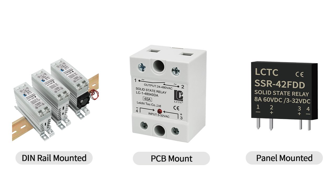
Types of SSR By Mounting Method
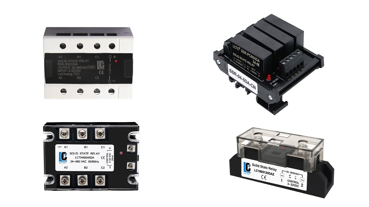
Depending on the mounting method, four types can be distinguished: DIN rail mounted, PCB mounted, bracket mounted, and panel-mounted.
DIN Rail Mounted SSR
Mounts on a standard 35 mm rail, making installation and removal easier. It allows quick installation and clear wiring; it is commonly used in control cabinets and industrial automation systems.
PCB Mounted SSR
They are installed directly onto a printed circuit board. Their compact size makes them suitable for space-constrained electronic and control applications.
Bracket Mounted SSR
It is mounted on a bracket or base and can be used with a heat sink.
Panel Mounted SSR
Secured to the control panel with screws, it is commonly used for high-current applications and should generally be used with a heat sink.
Choosing the appropriate installation method depends on your installation environment and available space for your equipment.
How to Choose the Right Solid State Relay
The categories of solid state relay are not mutually exclusive; a single SSR can fall into multiple categories at the same time. Take all these characteristics into account when selecting the appropriate SSR for your application.
Step 1 — Identify the Load Type
First, check whether your load is AC or DC. For an AC load, select an AC SSR; for a DC load, select a DC SSR. However, please note that the assessment should not be based on the control signal; it is essential to check the load side(output side).
Step 2 — Match the Input and Output Configuration
Once the load type has been confirmed, match the control signal to the load voltage.
| Control Signal (Input) | Load(Output) | SSR Configuration |
| DC | DC | DC-DC |
| DC | AC | DC-AC |
| AC | DC | AC-DC |
| AC | AC | AC-AC |
Step 3 — Choose the Switching Method
For most AC resistive loads, you can choose zero-cross SSR, because it can reduce switching transients, reduce EMI/noise, and is suitable for frequent ON/OFF switching, such as heaters, heating elements, ovens, and temperature control.
Random turn-on SSRs are suitable when the load needs to be switched at a specific point in the AC waveform.
Step 4 — Consider the Isolation Method
Next, consider how the control circuit should be electrically isolated from the load circuit.
For most industrial control applications, photo-coupled SSRs are a common choice because they provide electrical isolation without mechanical contacts. Such as PLCs, temperature controllers, industrial automation, and general-purpose control.
If your application requires transformer-based signal isolation and specific isolation or signal-transfer characteristics, you can consider a transformer-isolated SSR.
If you need sealed contact-based isolation method is required for specific low-level or specialized switching applications, you can consider reed-isolated SSR.
Step 5 — Select the Mounting Method
Choose the mounting method based on your available installation space, enclosure design, wiring requirements, and heat dissipation conditions.
| Installation Environment | Recommended Mounting |
| Industrial control cabinet | DIN Rail Mounted |
| PCB / electronic equipment | PCB Mounted |
| Custom mechanical installation | Bracket Mounted |
| Control panel | Panel Mounted |
Step 6 — Verify Electrical Ratings
As well as confirming the type of solid state relay, you must also check the rated load voltage and current; the SSR’s rated load voltage range must cover the actual load voltage. The rated current of the SSR must also be sufficient to handle the actual load current.
Given that SSRs may be subject to continuous current and derating, it is advisable to allow for a sufficient margin in the SSR’s rated current. In addition to this, the SSR’s surge voltage withstand capability must also be taken into account.
Step 7 — Check Heat Dissipation and Protection
Solid state relays tend to generate heat during operation; therefore, it is necessary to fit a heat sink for high-current applications. For certain resistive or inductive loads, additional protective components may need to be added to ensure the proper operation of the SSR. Common protection components include MOVs, RC snubbers, flyback diodes, fuses, and circuit breakers.
MOV (Metal Oxide Varistor): Frequently used in AC SSR switching devices, especially with inductive loads, to suppress surge voltages and transient overvoltages.
RC Snubber: Frequently used in AC SSRs, especially with inductive loads, to suppress voltage spikes and reduce rapid voltage fluctuations.
Flyback Diode: Used for DC inductive loads to protect the output switching devices.
Fuse or Circuit Breaker: Provides overcurrent and short-circuit protection for the solid state relay.
The specific protection requirements are based on the information provided in the solid state relay specification.

FAQ
What is the Typical Failure Mode of a Solid State Relay?
Common fault modes in solid state relays include short circuits at the output, which can be caused by excessive load current, high surge currents, or overheating.
A solid state relay can also fail in open-circuit failure. A common cause of this error is overheating. Due to the working principle of the internal semiconductor components of an SSR, it dissipates more heat than a mechanical relay during operation.
What Type of SSR Should I Choose for a Temperature Control System?
Using an example of a typical 24 VDC PLC or temperature controller controlling a 240 VAC single-phase heater inside an industrial control cabinet. Regarding the type of load, you need an AC SSR; however, considering the input and output, a DC-AC SSR is the more suitable choice.
Since the heating element is a resistive load, the use of a zero-cross SSR is recommended. You may choose a photo-coupled SSR to achieve galvanic isolation between the PLC control circuit and the heating circuit. For installation in the control cabinet, finally select an solid state relay for the DIN rail.
Therefore, for this application, a suitable SSR configuration would be DC-AC, zero-cross, photo-coupled, and DIN rail-mounted. In making your specific choice, you should also consider the parameters of the heating element, installation conditions, and requirements for heat dissipation.
What Type of SSR Should I Choose for a DC Motor?
Let’s take as an example a common 24 VDC PLC controlling a 24 VDC DC motor in an industrial control cabinet. Regarding the type of load, the motor is a DC load; therefore, considering the input and output voltages, a DC-DC SSR is the more suitable choice.
For controlling DC motors, both zero-crossing control and random turn-on are not particularly suitable. The required switching behavior depends on whether the application uses simple ON/OFF switching or high-frequency PWM control.
If the PLC and motor circuit need electrical isolation between them, you can choose a photo-coupled SSR. Finally, for installation in a control cabinet, a DIN rail-mounted SSR is a practical choice.
When making a practical selection, you also need to consider various motor parameters and the thermal environment.
What Type of SSR is Best for Inductive Loads?
There is no single solid state relay type suitable for all inductive loads; analysis must be performed according to the specific load.
Inductive AC loads typically use AC SSRs. When precise control of the switching point is required, solid state relays with random turn-on are better suited; zero-cross SSRs are also suitable for many applications.
For DC inductive loads, use a DC SSR. Zero-cross and random turn-on are AC switching modes and therefore do not apply to DC SSRs.
In addition to selecting the appropriate type, inductive loads must also be properly protected according to specific conditions, as voltage spikes may easily occur during switching off.
What Type of SSR is Best for Resistive Loads?
Although resistive loads exhibit a relatively stable current characteristic, the solid state relay must be selected according to whether the load is AC or DC.
For resistive AC loads, AC SSRs with zero-crossing control are typically used. For resistive DC loads, a DC SSR should be selected.
Regardless of which variant you choose, make sure that the rated voltage and rated current match, and also consider heat dissipation.
Final Thoughts
The classification of solid state relays is not mutually exclusive; a single SSR can belong to multiple categories simultaneously. LCTC offers a wide range of solid state relays that cover various load types, different input and output configurations, diverse switching modes, and mounting requirements. Please browse our range of solid-state relays to find the solid state relay configuration that best suits your application requirements.