Relays are widely used in industries such as industrial automation, climate technology, and new energy. But do you know which of the two most common relays, solid state relay or mechanical relays, is better suited for your application? This article provides a detailed analysis of the differences between them to help you choose the relay best suited for your application.
What are the Fundamental Differences Between SSR vs EMR?
The fundamental difference between solid state relays and mechanical relays lies in their switching mechanism, i.e., in their different operating principles, which leads to differences in their characteristics and application areas.
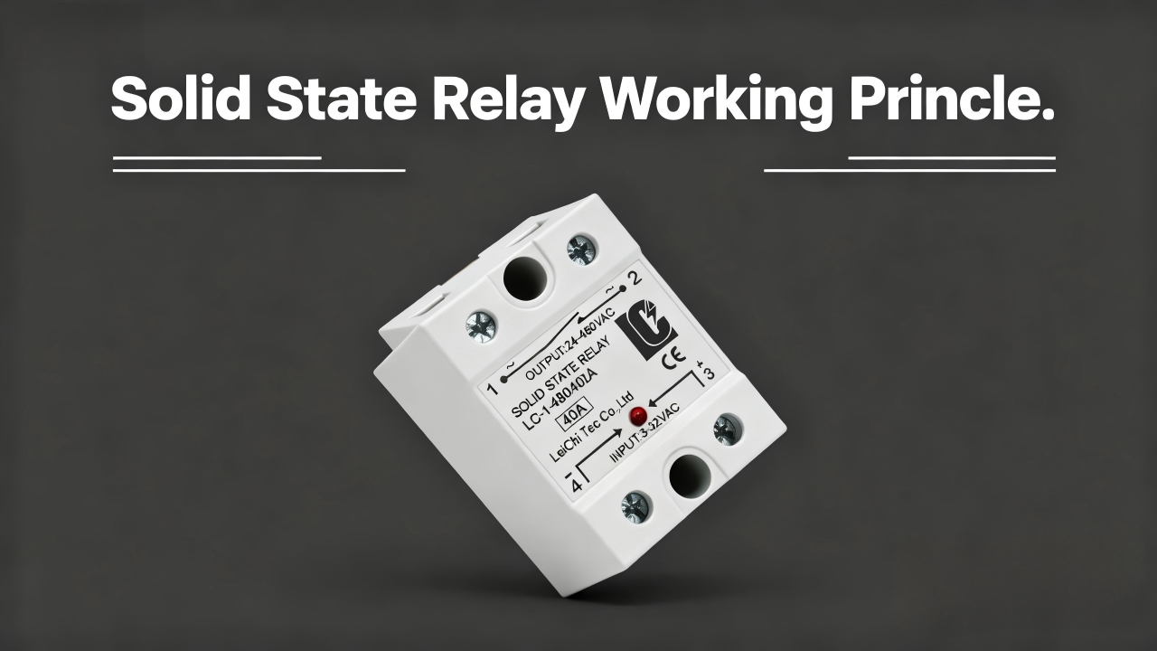
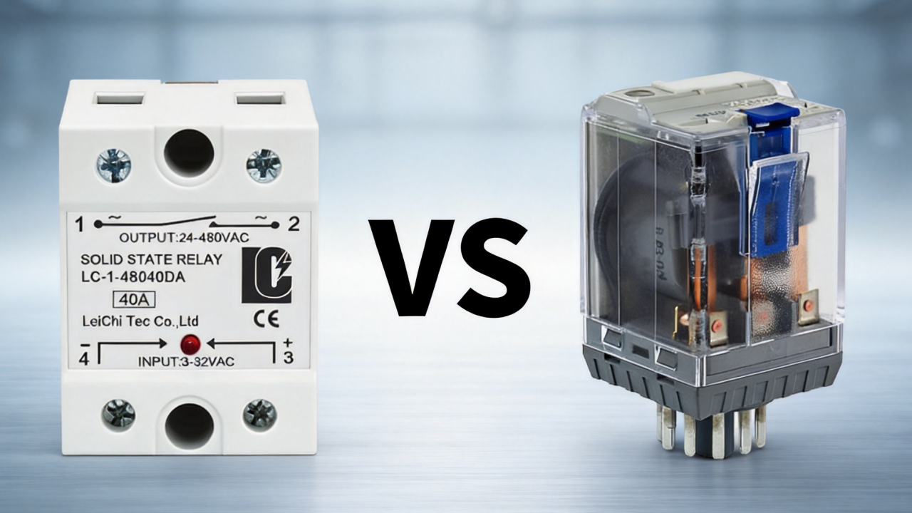
A solid state relay is an electronic switch primarily composed of optocouplers, a control circuit, MOSFETs, and other semiconductor components.
It controls semiconductor components via control signals supplied through the input circuit, thereby regulating the turning on and off of the current. This electronic component is characterized by fast switching, low noise, and wear-free operation.
A mechanical relay is a type of switch whose internal structure includes a coil, an anchor, an iron core, a spring, metal contacts, and so on.
A low-power voltage is applied to control the coil, creating an electromagnet. The electromagnetic force pulls the armature, causing physical movement that activates a series of mechanical connections, thereby closing the contacts and completing the main circuit.
The interruption of the circuit occurs when the electromagnetic field disappears, the spring pulls the armature away, the contacts separate, and the circuit is broken.
What are the Key Differences Between SSR vs EMR?
Solid state relay vs electromechanical relay: In addition to the fundamental differences, there are six other key factors that make a detailed comparison worthwhile. Below, solid state relays and mechanical relays are thoroughly compared from various perspectives, from reliability and switching performance to load compatibility, heat management, and overall cost.
1. Reliability and Lifetime Comparison
Solid state relay do not use any mechanical components, resulting in no wear and no contact arcing. They can be switched on and off millions or even tens of millions of times, offer a long service life, and are characterized by relatively high reliability.
However, the lifespan of SSRs is susceptible to overvoltage, short circuits, and heat generation.
The mechanical contacts of an electromechanical relay are prone to physical wear and oxidation, as well as coil failure, which limits their lifespan to thousands to millions of switching cycles. Additionally, they can be easily damaged by strong vibrations and impacts, resulting in relatively low reliability under such conditions.
Therefore, when you are installing a mechanical relay, pay attention to the mounting location and avoid placing it in areas where strong vibrations occur.
2. Switching Speed and Frequency Comparison
Solid state relays have no physical limitations and are extremely fast, typically reaching speeds in the microsecond range. Additionally, the SSR supports high-frequency switching with frequencies ranging from several dozen Hz up to the kHz range, enabling precise control and rapid load switching. If you need a switching method with fast switching, you can opt for an SSR.
The mechanical movements of a mechanical relay, such as the contact movement and the spring’s return speed, limit the switching speed, causing the switching to generally occur slowly and typically taking between 5 and 15 milliseconds.
Additionally, the switching frequency of EMR is typically below a few dozen Hz, making it unsuitable for high-frequency switching operations and only suitable for low-frequency control.
3. Load Compatibility Comparison
Solid state relays are particularly suitable for controlling ohmic loads due to their characteristics such as high-frequency operation, radio frequency-free function, and long service life. Typical ohmic loads include industrial furnaces, electric heating devices, and heating pipes.
SSRs with overvoltage protection are suitable for inductive loads; additionally, an appropriate protective circuit is required. Typical inductive loads include electromagnetic coils, solenoid coils, solenoid valves, transformers, etc.
Capacitive loads generate higher overvoltages, making SSRs more vulnerable; therefore, additional overvoltage protection devices and soft-start circuits are required. Typical capacitive loads include switching power supplies, LED drivers, and similar components.
Mechanical relays have no leakage current and require no minimum load. They can be used for ohmic loads, although their lifespan may shorten under high-frequency switching conditions. In contrast, they offer better load handling capabilities for inductive and capacitive loads. Therefore, you can use the EMR in environments without high frequencies for most loads.
4. Heat Dissipation and Thermal Management
In solid state relay components, a voltage drop occurs in the on-state, resulting in energy loss. This energy is converted into heat; the greater the load, the more heat is generated.
The metal contacts of an electromechanical relay offer lower resistance, generating minimal heat and usually requiring no additional measures for heat dissipation.
5.Cost and Long-Term Value Comparison
Due to semiconductor components, control circuits, and heat dissipation, solid state relay have higher upfront costs, but they are more durable, reliable, require less maintenance, cause shorter downtime, and have a longer lifespan. If you used in high-demand applications, it is more cost-effective in the long run.
Since mechanical relays have a proven design and low manufacturing costs, their initial purchase price is relatively low; however, they offer lower reliability and shorter service life in applications involving frequent switching.
They may require more frequent maintenance and replacement, which also increases operating costs, and have a shorter lifespan, thereby raising the long-term expenses for EMR use.
Quick Comparison: Solid State Relay vs Mechanical Relay
Regarding the two most commonly used types of relays—solid state relays and mechanical relays. Due to different switching mechanisms, there are various differences in performance characteristics, application areas, and costs. The following table provides a brief overview of the main differences.
Solid State Relay VS Mechanical Relay | ||
Dimension | Solid State Relay | Mechanical Relay |
| Principle | Semiconductor devices enable electronic switching without any mechanical movement | An electromagnetic coil drives mechanical contacts to act as a physical switch |
| Switching Speed | fast | slow |
| Switching Frequency | Supports high-frequency, high-cycle switching. | High-frequency switching is limited. |
| Load Compatibility | Suitable for resistive loads; when controlling inductive loads, inrush current and protective measures must be considered. | It can directly control various resistive, inductive, and capacitive loads. |
| Lifespan | Hundreds of millions of cycles / Long MTBF | Limited service life |
| Heat Dissipation | High currents require the use of a heat sink | Low heat dissipation requirements |
| Isolation | Optical isolation is typically used to isolate the control side from the load side. | Provides electrical isolation via physical contacts |
| Electric Arc | Arc-free | There is a risk of an electric arc |
| Performance in Harsh Environments | More resistant to vibration and mechanical shock, but sensitive to overheating and overpressure | It is fairly tolerant of temperature shocks, but the mechanical environment may affect its service life |
| Leakage Current | Yes | No |
| Cost | High initial costs, but good value for money in the long term | Low initial costs, but high long-term maintenance costs |
| Applications | Industrial heating, temperature control equipment, automation equipment, high-frequency control | General-purpose control, motor control, power supply switching, etc. |
| Noise | Quiet operation | There is mechanical noise |
| Shock and Vibration Resistant | Strong | Susceptible to environmental influences |
| Size | Small | Larger |
| Internal Structure | Input stage, opto-isolation, electronic control drive, power semiconductor output stage. | Coil, electromagnet, spring, mechanical contacts |
| On-State Resistance | High | Low |
| Electromagnetic Interference | Low | High |
| Wear and Tear | No mechanical wear | Contact wear, spring fatigue, arc damage |
| Positional Sensitivity | Can be installed in any position | Certain mechanical structures may be affected by their orientation and vibration. |
Can Solid State Relay Replace Mechanical Relay?
Yes, solid state relay can replace mechanical relays in many applications. However, SSR is not suitable for all applications; for some applications, EMR is a better fit.
The specific choice depends on the particular requirements of the application, such as the type of load, switching frequency, thermal dissipation requirements, and demands for reliability and cost.
When Should You Use a Solid State Relay
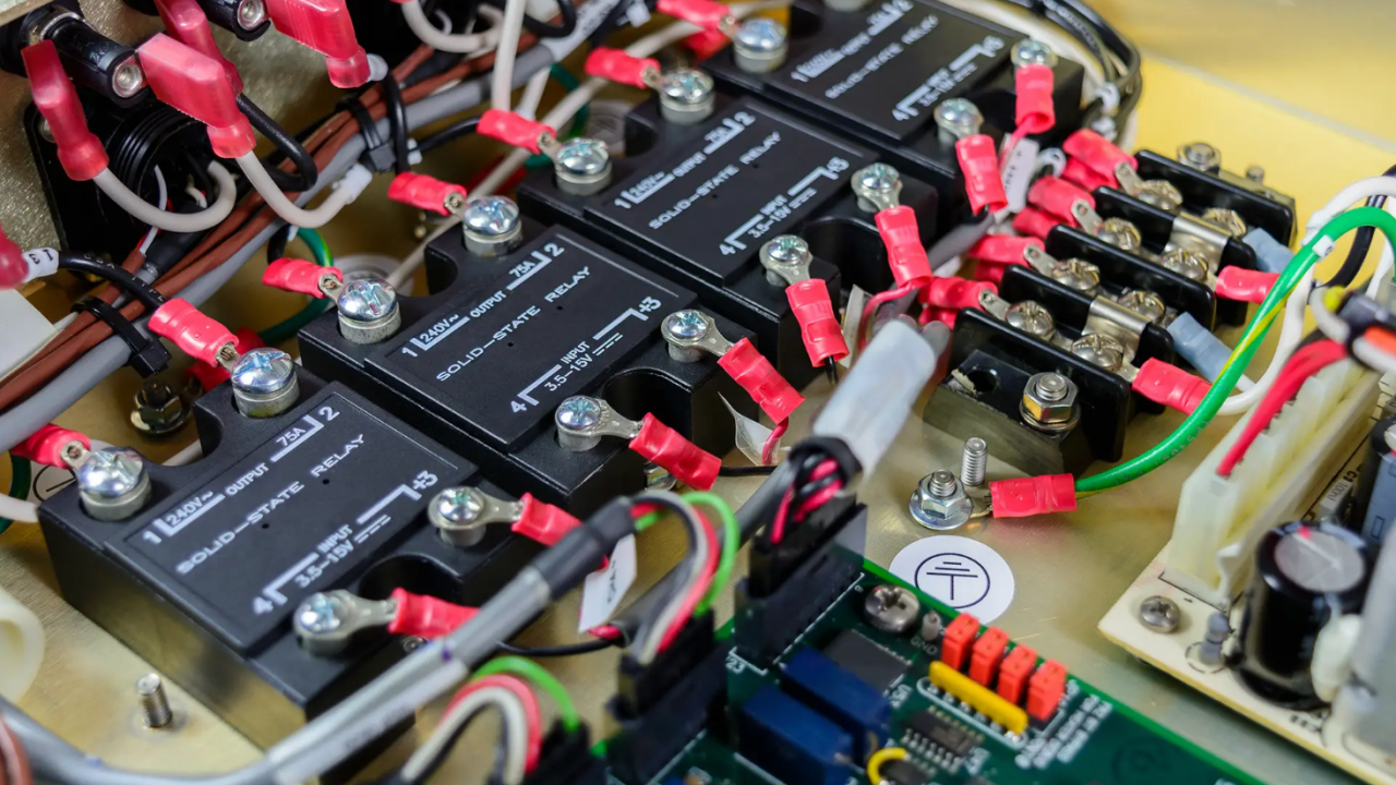
Solid state relays offer advantages such as fast, high-frequency, and precise switching control, high stability, long service life, continuous operation, and excellent environmental resistance. They are therefore suitable for devices requiring frequent switching, precise control, and continuous operation, as well as for harsh industrial environments.
Typical applications include PLC automation systems, temperature control systems, packaging and processing machinery, injection molding machines, food processing, and HVAC systems.
However, SSR has certain limitations that must be avoided through specific measures:
- Overheating: The greater the load, the more heat the SSR generates.
Solution: Select an appropriately rated current and operate the device with reduced power. Pay attention to temperature and ventilation conditions in the installation environment; if necessary, a heat sink must be installed.
- Leakage Current: Due to the operating principle of the SSR, complete isolation is not achieved even in the off state, resulting in a small current flowing.
Solution: Install a discharge resistor and verify the minimum load requirements.
Please Notice: In circuits involving emergency stops or physical safety barriers, SSRs alone are not sufficient; an EMR or contactor must be connected in series to act as the primary physical disconnect.
- Surge Current or Short Circuit: The semiconductor components inside the SSR have limited tolerance for short-term overcurrents and transient stresses.
Solution: Installation of fuses, varistors, or other overvoltage protection measures.
- Load Compatibility: With inductive or capacitive loads, issues may arise when using standard zero-crossing SSRs.
Solution: Depending on the specific circumstances, protective measures such as RC snubbers, MOVs, or soft-start circuits should be added.
When Mechanical Relay Is Still Preferred
Mechanical relays are characterized by low heat generation, low cost, true electrical insulation, and wide load compatibility, making them particularly suitable for applications with limited budgets, low switching frequencies, and simple control logic, or high impulse current loads, as well as easy replacement, small signal circuits, and other general industrial equipment.
Examples include electric motors, transformers, solenoid valves, emergency stop circuits, battery-powered devices, etc. However, electromechanical relays have numerous limitations that must be avoided through specific measures:
- Contact Wear: The long-term, repeated mechanical movements of a mechanical relay can cause slight oxidation and wear of the internal contacts.
Solution: You can select suitable contact details, reduce the switching frequency, and perform regular maintenance.
- Noise and Arc: When closing the contacts, cracking sounds and electrical arcs may occur, which can lead to electromagnetic interference and contact wear.
Solution: Install a gas discharge suppression circuit, an RC snubber, or an MOV.
- Coil EMF Kickback: When current to the coil is cut, the disappearance of the magnetic field results in a voltage peak in the opposite direction, the voltage spike may damage the control system.
Solution: Place a flyback diode in parallel with the coil.
- Contact Bounce: Mechanical contacts can easily cause fluctuations, which may lead to unstable signals or logic errors.
Solution: Introduce a debounce circuit or time delay.
How to Replace Mechanical Relay with SSR Successfully
If you intend to replace the original mechanical relay with a solid state relay, you can follow these four steps:
- Verification of the Original EMR Parameters
These include the supply voltage, load voltage, load current, load type, switching current, etc. After verifying that the SSR parameters are compatible, the replacement can proceed.
- Selection of the Appropriate SSR Type
Select the appropriate SSR based on the original parameters, for example, whether it involves controlling a DC or AC circuit, whether a zero-crossing SSR is required, and whether random switching or overvoltage protection is needed when controlling motors or transformers.
- Whether Modifications to the Electrical Design are Required
Additional electrical components such as fuses, MOVs, RC snubbers, and heat sinks can be added to the SSR installation if needed.
- Test After Replacement
Test SSR using methods such as switching tests, temperature rise tests, load-start tests, insulation tests, tests under actual load, and long-term operating tests, among others.

How to Select the Right Solid State Relay for Your Application
With a suitable solid state relay, you can achieve faster and more precise control in your application, allowing devices to perform at their best.
When selecting an appropriate SSR, five key factors should be considered: load type, current rating, rated voltage, heat dissipation, and switch type.
Step 1: Determine Load Type
There are three types of loads: resistive loads, inductive loads, and capacitive loads.
Resistive loads: For resistive loads such as industrial ovens, heating elements, electric ovens, etc., the use of a zero-crossing SSR is recommended.
Inductive Loads: If your load is an electric motor, solenoid valve, transformer, or a similar inductive device, we recommend using an SSR with overvoltage protection and additional protective measures.
Capacitive Loads: For capacitive loads such as switching power supplies or LED drivers, it is recommended to use an SSR with overvoltage protection or a soft-start circuit.
Step 2: Calculate Current Rating
First determine your load current, which is typically calculated based on power (P)/voltage (V). It is recommended to select a rated current that is approximately 1.5 to 2 times the actual load current to improve reliability. If your load current is, for example, 14A, the recommended rated current is 14 × 1.5 = 21A. Therefore, we recommend selecting a 25A SSR.
Please note that higher surge currents may occur with inductive and capacitive loads; it is recommended to select a current rating 2 to 3 times the rated current.
Step 3:Select Voltage Rating
Determine whether your load is DC or AC. The SSR’s rated current must generally be higher than the load’s maximum operating current. For a 24VDC load, for example, an SSR with 5–60VDC is recommended, while for a 220VAC load, an SSR with 24–480VAC is suitable.
Step 4: Consider Heat Dissipation
First, the heat generation of the SSR is calculated, which typically results from multiplying the load current by the voltage drop across the SSR in the on-state (usually 1–1.6V).
To select the appropriate heat sink, its thermal resistance (Rth) must be calculated, which is typically given by the formula (Tj – Ta)/P = Rth. Here, Tj is the maximum junction temperature of the SSR, Ta is the ambient temperature, and P is the power dissipation of the SSR.
Ensure adequate ventilation during installation and avoid excessively high ambient temperatures whenever possible.
In summary, when selecting heat sinks, it is recommended to use small heat sinks for short-term operation and low current loads. The larger heat sinks should be chosen for continuous operation and high current loads. In environments with high temperatures, the rated power of the SSR should be reduced and the heat sink enlarged accordingly.
Step 5: Choose the Right Switching Mode
Zero-crossing SSR: Can reduce switching current and electromagnetic interference in certain applications, suitable for resistive loads; however, it is generally not suitable for applications requiring phase angle control or fast response times.
Random turn-on SSR: Provides faster response time, supports power regulation, and is suitable for applications requiring rapid on/off operations and phase angle control. However, depending on the specific load requirements, configuration of an RC snubber, MOV, and additional measures to protect against electromagnetic interference may be necessary.

FAQ
What Types of Solid State Relays?
Depending on the output power or load type, there are differences between DC solid state relays and AC solid state relays.
Depending on the type of input and output, four types can be distinguished: DC control of DC, DC control of AC, AC control of DC, and AC control of AC.
Depending on the insulation type, they are classified into photo coupled SSRs, transformer insulated SSRs, reed insulated SSRs, and hybrid SSRs.
Depending on the operating mode, SSRs are divided into normally open and normally closed.
Depending on the switching method, they are classified into zero-crossing SSR, random turn-on SSR, and peak sensing SSR.
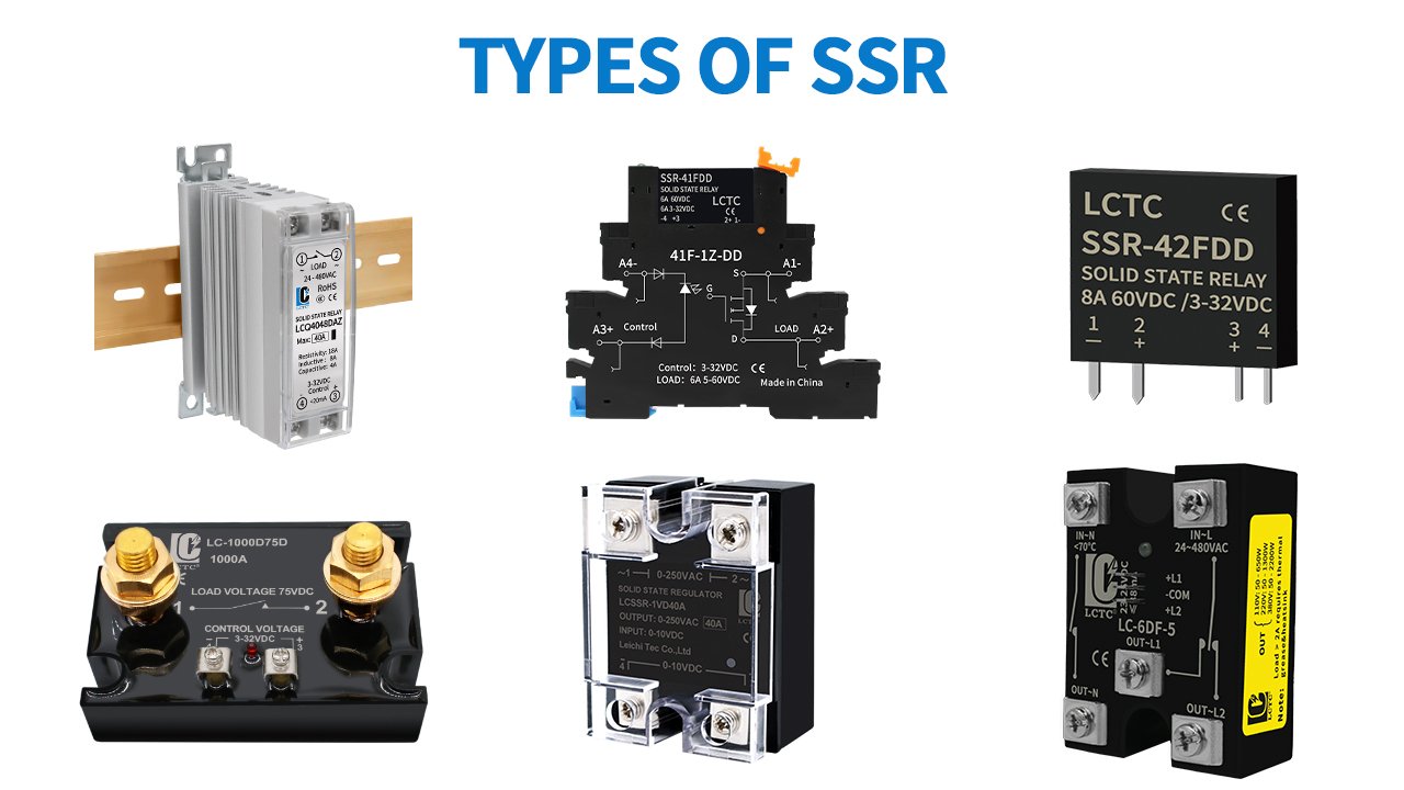
Depending on the mounting type, SSRs can be categorized as follows: DIN rail mounted SSR, PCB mounted SSR, bracket mounted SSR, panel mounted SSR.
What Types of Electromechanical Relays?
Common EMR types include general purpose power relay, power relay, time delay relay, latching relay, reed relay.
Is the SSR in an Open-Circuit or Closed-Circuit State When it Fails?
Both are possible, but short circuits occur most frequently. Interruptions are relatively rare but can also happen, for example due to damaged internal components or faulty solder joints.
Why is the Rated Current of an SSR Higher than the Load Current?
In practice, SSRs may experience issues such as overheating, load fluctuations, and starting current surges. The rated current is higher than the load current to counteract these problems and ensure stable operation.
Why Can’t an SSR Directly Replace a Contactor?
The two differ in their function: SSRs are primarily used for fast, frequent, and precise switching operations, whereas electronic controls cannot achieve complete physical separation.
Contactors are primarily used to switch high power ratings and large currents, and are suitable for controlling the main power supply.
If you need an exchange, it must be checked whether requirements such as load type, power capacity, starting current, and safety requirements are compatible.
Does an SSR Consume Power When It Is Switched Off?
After turning off, there may be a slight power consumption, but no significant loss occurs as in the on state.
What Is the Difference Between AC SSR and a DC SSR?
The internal switching elements and the controlled load voltages of the two differ.
AC SSRs typically use bidirectional thyristor components (TRIACs) or thyristor rectifiers (SCRs) to control AC loads.
DC SSRs use MOSFET or IGBT switching elements to control DC loads.
Can a Solid State Relay Control a Contactor Coil?
Yes, the coil is an inductive load, so starting current protection and overvoltage protection must also be taken into account.
Can Solid State Relays Be Used in Outdoor Applications?
Yes, but this depends specifically on external conditions. In outdoor environments with moisture, dust, and high temperatures, additional protective measures are required, such as protective covers, heat dissipation methods, and moisture protection measures.
Final Thoughts
At LCTC, we offer you a comprehensive range of solid state relays, including SSRs for various load types in both DC and AC applications, as well as single-phase and three-phase SSRs for controlling different numbers of power supplies.
Feel free to browse our range of semiconductor relays or contact us for technical support and customized solutions.