
A solid state relay is a type of electronic component. Do you know how to wire a solid-state relay? In this article, we’ll learn together how to wire solid state relays into common electrical systems. Read this article to learn more wiring techniques, and you too will be able to integrate solid-state relays into electrical systems.
Understanding Solid State Relay Terminal Structure
The terminals of a solid state relay are generally divided into two sides: the input (control side) and the output (load side). The input terminals receive the control signal, while the output terminals switch the load current.
SSR Input Terminals (Control Side)
A low-power control signal and a relatively small current are usually required at the input. Common ranges include 3–32 VDC or 4–32 VDC, used for connecting devices that send control signals. Simply put, it involves controlling the switching operations of an SSR. Common devices include temperature controllers, PID controllers, PLCs, microcontrollers, and switches.
However, note that polarity must be observed at DC input terminals; plus and minus cannot be reversed. For AC inputs, no polarity distinction is required; AC control signals can be connected directly.
SSR Output Terminals (Load Side)
The output terminals connect the SSR to the power supply and load and carry the load current when the SSR is conducting. For AC solid state relays, aspects such as rated output voltage, rated load current, and the type of AC load must be considered due to higher load currents at the output.
Especially compatibility with loads, as additional protective measures for the SSR may be required for resistive and inductive loads. With DC SSRs, you must also ensure that polarity is not reversed and that the load is protected.
How to Identify SSR Input and Output Terminals
The input and output terminals of a solid state relay can be identified by the terminal markings and product label; these are usually clearly marked on the SSR.
Generally, DC control signals are marked with “+/-“, while AC control signals are typically indicated at the input with “~ ~” and at the output with “~ ~”, “1-2”, or “L1-L2”. Please note that slight variations in notation may occur depending on the manufacturer.
SSR Type | Input Terminal (Control) | Output Terminal (Load) |
| + / – | + / – | |
AC-DC SSR | ~ ~ | + / – |
| DC-AC SSR | + / – | ~ ~ / 1-2 / L1-T1 |
| AC-AC SSR | ~ ~ | ~ ~ / 1-2 / L1-T1 |
Basic Solid State Relay Wiring Diagram
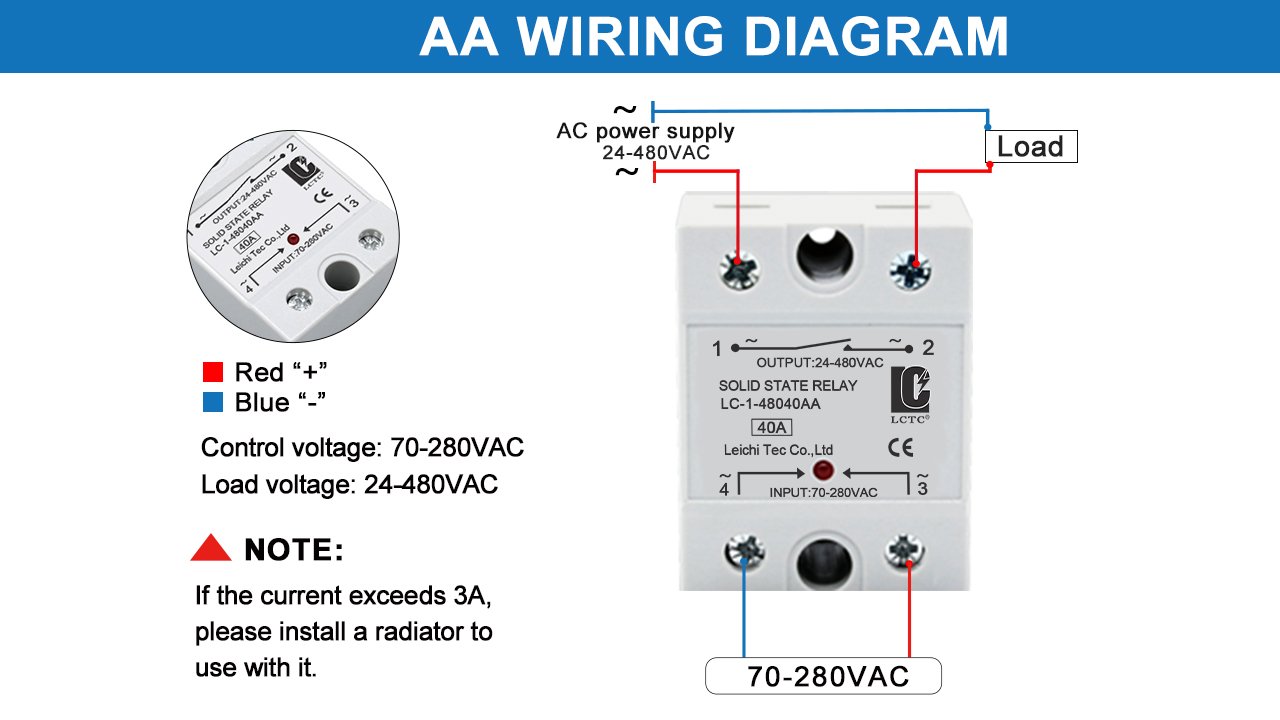
A complete solid state relay control system typically includes control devices, SSRs, a power supply, and the load.
The controller sends a low-power control signal to the solid state relay input. Once the SSR input receives the control signal, the input circuit transmits it through an optocoupler isolation to the output side and activates the power semiconductor devices.
When the SSR turns on, the output circuit is completed and current flows through the load.
The power supply on the load side is connected in series with the solid state relay output and the load. When the SSR is turned on, current flows through the SSR output and the load, thereby supplying power to the load and enabling its operation.
Please note the following when you are connecting the wires:
Correct connection of the input and output terminals of a solid state relay.
Verification of voltage compatibility.
Selection of the appropriate rated current.
AC and DC Solid State Relay Wiring Differences
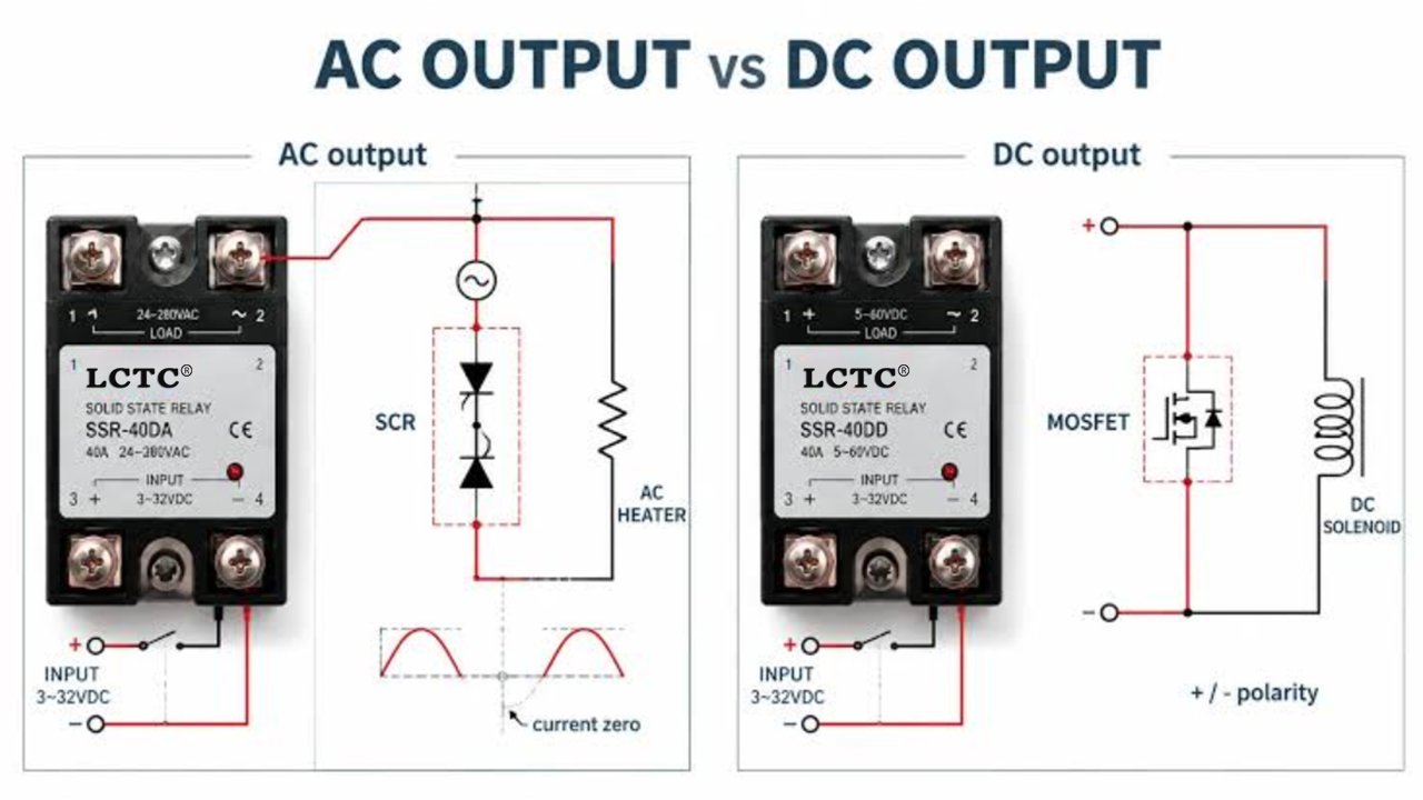
When deciding between an AC SSR and a DC SSR, the type of load at the output is a crucial factor. However, due to the characteristics of AC and DC circuits, their wiring methods and protection requirements also differ.
An incorrect selection may cause the solid state relay to fail, disrupt the load, or even damage the control device. AC SSR and DC SSR cannot be directly interchanged, as the output switching devices of both types are designed for different electrical characteristics.
AC Solid State Relay Wiring
AC solid state relays are primarily used to switch AC loads such as heating systems, industrial ovens, AC motors, and lighting loads, covering both DC-AC and AC-AC applications.
AC solid state relays typically have no fixed polarity, so there is no need to distinguish between positive and negative when you are connecting the load; however, it must be ensured that the voltage and current parameters match.
You must also consider the type and compatibility of the AC load, especially with inductive loads, as switching inductive loads can generate voltage spikes that may damage the output components in the SSR.
To avoid this, one can opt for a zero-cross SSR or implement protective measures such as MOVs or RC snubbers.
AC SSR also comes in the variants “Single-Phase” and “Three-Phase,” with the main difference lying in the type of controlled power supply system and the size of the load.
- Single-phase SSRs are typically used to control single-phase AC loads, with the output connected in series between the single-phase power supply and the load.
- Three-phase SSRs are used to control three-phase AC loads and are commonly employed in large industrial systems. They use three AC lines/phases to control a three-phase load. Depending on the solid state relay configuration, either individual or all circuits can be controlled simultaneously to ensure reliable switching of the load.
Note: In most single-phase AC applications, the SSR is installed in series with the line (L) conductor rather than the neutral (N) conductor, so that when turned off, it can interrupt the connection between the load and the power supply, thereby enhancing system safety.
DC Solid State Relay Wiring
DC solid state relays are specifically designed for switching DC loads such as DC motors and solenoid valves, common DC SSR configurations include DC-DC and AC-DC types.
Unlike AC SSRs, DC SSRs have polarity-sensitive terminals, and the plus and minus terminals must be clearly marked when connected; connections must strictly follow this designation.
You must also consider the type of load and compatibility, especially with inductive loads, when an inductive load is switched off, the collapsing magnetic field can generate a back EMF that may damage the internal components of the solid state relay. This can be prevented by protective measures such as installing a flyback diode or a TVS diode.
4 Practical Solid State Relay Wiring Diagram Examples
Among the various industrial applications of solid state relay, the following five scenarios represent the most typical uses, including temperature control, PLC control, switching power supplies, and motor control.
Temperature Controller + SSR + Heater Wiring
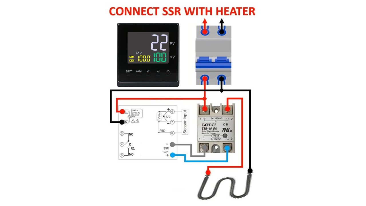
This is one of the most typical applications for solid state relays: the temperature controller outputs a control signal that switches the heating load via the SSR.
First, the output of the temperature controller is connected to the input of the SSR; the temperature controller sends a control signal to regulate the SSR’s switching state.
Then you can connect the line (L) of the AC line to one side of the output, and the other side of the output to the heating element.
The other end of the heating element is connected to the neutral (N) of the AC power supply, forming a closed load circuit.
The temperature controller sends a control signal, which activates the SSR. Current flows through the SSR and the heating element, causing the heating element to turn on; the control signal is interrupted, the SSR is deactivated, and the heating element switches off.
It should be noted that heating devices fall under resistive loads and are therefore suitable for use with zero-cross AC SSRs.
PLC + SSR + Industrial Load Wiring
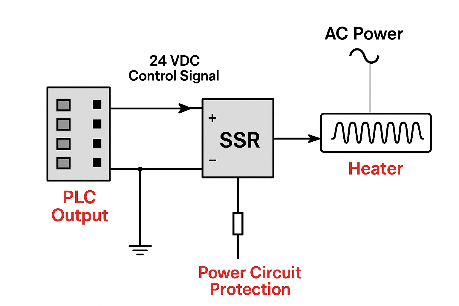
This is typically used in automated systems for controlling industrial loads, which are frequently switched on and off. The electrical isolation between the PLC and the load is achieved via an SSR.
First, the digital output of the PLC is connected to the input of the solid state relay, the power supply is connected to the SSR output, and an industrial load is connected in series across the other side of the output.
The solid state relay input receives the signal emitted by the PLC, which triggers the internal switching components and closes the load circuit.
Switching Power Supply + DC SSR + DC Load Wiring
This circuit is primarily used to control DC loads. When wiring, the polarity must be strictly observed.
First, connect the AC power supply to the input of the switching power supply to convert the alternating current into direct current. The positive terminal of the switching power supply is connected to the positive terminal of the solid state relay output.
On the other side of the solid state relay output, the positive terminal of the DC load is connected. The negative terminal of the DC load is connected to the negative terminal of the switching power supply, forming a closed DC circuit.
The control device is connected to the SSR input to control the on or off of the load.
Motor Control with SSR Wiring
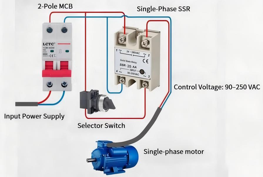
This application primarily concerns AC motors with inductive loads. Since high starting currents may occur during startup, proper selection is necessary; additional protective or auxiliary devices may be required in some cases. The following switching instructions serve as an example for a single-phase motor.
First, connect the output signal of the control device to the input of the solid state relay.
Connect the line (L) to one output terminal of the SSR, and connect the other output terminal to the motor.
The other end of the motor is connected to the neutral (N) of the AC power supply, and the SSR switches the motor’s circuit based on the received control signal.
For motors with high inrush current, the solid state relay current rating should be selected based on startup conditions rather than only the rated running current.
Common SSR Wiring Errors & Troubleshooting Guide
If your SSR is incorrectly wired, an unsuitable model has been selected, or protective measures are inadequate, this may result in SSR failure or load malfunction, SSR testing is required to identify the source of the fault. Below are common wiring errors.
1. The Load is Connected to the SSR Input
The SSR input requires only a small amount of current and cannot carry load current.
- Problem: This may result in the SSR not switching on, the controller being damaged, or damage to the input circuit.
- Solution: Before connecting, please ensure that the control device is connected at the input, and that the power supply and load are connected at the output.
2. DC SSR Polarity Reversed
The direction of the direct current is fixed; the positive and negative terminals must be connected according to the terminal markings.
- Problem: Problems such as the load failing to start, the SSR not functioning, or outright damage may occur.
- Solution: Before connecting, check the label on the terminals: positive (+), negative (-).
3. Selecting the Wrong AC/DC SSR Type
AC and DC solid state relays differ in their internal switching components: AC SSRs typically use triacs or SCRs as output switches, whereas DC SSRs usually employ MOSFETs or IGBTs. These two types are not interchangeable.
- Problem: This may cause it to fail to switch properly or even become damaged, resulting in the load no longer functioning.
- Solution: Select the appropriate one according to the load voltage, load current, and AC or DC load type.
4. Using Incorrect SSR Input Voltage
The supply voltage doesn’t match the specifications of the SSR input.
- Problem: This may result in damage to the input circuit or a failure of the SSR.
- Solution: Check the input type and input voltage range before connecting.
5. Ignoring Inductive Load Protection
When the load is turned off, voltage spikes or back EMFs may occur easily in AC and DC SSRs.
- Problem: This may lead to damage of the semiconductor components in the SSR.
- Solution: MOVs and RC snubbers can be added to AC SSRs, while flyback diodes and TVS diodes can be added to DC SSRs.
FAQ
How to Choose the Right SSR for My Application?
First, you need to determine the requirements for the load voltage and load current to ensure that the SSR has a sufficient margin. Take into account the type of current and the nature of the load. In applications involving high currents, heat dissipation must also be considered.
Can an SSR Control Both AC and DC Loads?
No, a single SSR device cannot simultaneously control AC and DC loads; the correct model must be selected.
Why Does My SSR Overheat?
Overheating of the SSR is usually caused by excessive load current, insufficient heat dissipation, high ambient temperature, or an unsuitable solid state relay selection. Unlike mechanical relays, an SSR generates heat during operation. Therefore, in certain applications involving high voltage and high current, heat dissipation must be carefully considered. By installing heat sinks and implementing measures to maintain proper ventilation in the surrounding environment, overheating of the SSR can be prevented.
Does an SSR Need a Heat Sink?
Not always, heat sinks are among the most commonly used methods for heat dissipation in SSRs. Higher-current SSRs often require a properly sized heat sink.
Why Does My SSR Stay ON Even When the Control Signal Is OFF?
This can be caused, among other things, by an SSR leakage current, wiring error, incompatible load, or a defect in internal components. Due to the working principle of SSR semiconductor components, a small leakage current may still occur in the off state.
When it is fully in the on state, please check whether the input signal has been completely switched off, whether the connections are properly wired, and whether the SSR has been damaged by overcurrent, voltage spikes, or overheating.
Can an SSR Switch High-Frequency Loads?
Yes, since SSRs switch using semiconductor components and have no mechanical contacts, they exhibit low wear and can withstand several million switching cycles, making them highly suitable for applications requiring high-frequency switching.
What Safety Precautions Should Be Noted When Connecting Solid State Relays?
When wiring solid state relays, it is essential to ensure that the power supply is interrupted, all parameters meet the application requirements, the type of load is verified, and appropriate protective components are installed if necessary. For high current levels, heat dissipation must be taken into account.
Final Thoughts
Proper wiring helps ensure reliable and stable performance of the solid state relay as well as a longer service life. LCTC offers you a comprehensive range of solid state relays specifically designed for various industrial applications.
If you are looking for a reliable SSR manufacturer or need OEM support, feel free to contact LCTC. We offer a variety of SSR types for you, and we also offer assistance with product selection and technical advice.