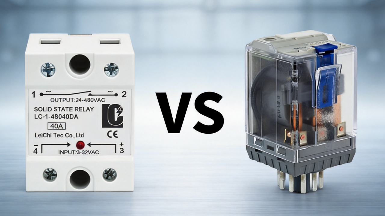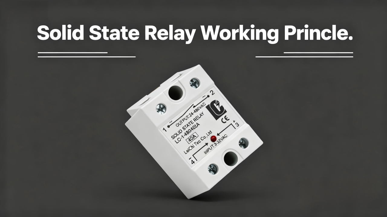
Solid state relays are commonly used in various industrial systems. However, problems may arise when using them that can affect the switching performance and reliability of the system. Therefore, it is crucial to quickly inspect SSRs. In this article, you’ll learn how to test SSRs in various ways and identify common failure modes.
Preparations Before Solid State Relay Testing
Safety Precautions
- 1. For safety, the power supply should be disconnected before you connect or check.
- 2. During voltage testing, exposed connections must not be touched.
- 3. Never use test conditions that exceed the rated voltage or rated current of the SSR.
- 4. After completing the procedure, make sure the SSR and the heat sink are cooled down before taking any further actions.
- 5. Work on high-voltage or high-current circuits should be carried out by qualified personnel.
- 6. If necessary, appropriate personal protective equipment (PPE) must be worn.
Preparation Before Testing
- 1. You should check the solid state relay’s technical specifications, including input voltage, output voltage, rated current, AC or DC output, and terminal configuration.
- 2. Testing tools: Keep a digital multimeter, a power supply, an appropriate test load, connecting leads, and a screwdriver ready. You should also have insulation tools available if needed.
- 3. Please note that the test environment must be secure and stable, with sufficient cabling and adequate space for operation.
Step-by-Step Guide: How to Test an SSR
There is no single test that can definitively confirm whether an solid state relay functions properly. Therefore, when you are testing solid state relay, various methods must be used, along with the technical specifications provided by the SSR manufacturer and the actual operating conditions.
Visual Inspection
- First, you should check the condition of the SSR housing: inspect whether the housing shows cracks, deformations, burn marks, melting traces, or significant discoloration.
- Then you can check the condition of the SSR terminals: Are the screws loose, discolored, damaged, or burned, or do the terminals show obvious irregularities.
- Finally, check the heat sink and installation: Is the heat sink loose, showing visible damage, or does the installation have irregularities.
Check SSR in particular for signs of overheating, including discoloration of the housing, melted plastic, burn marks, heat damage around the terminals, and any abnormalities on the heat sink.
In summary, it can be stated that if the relay shows severe burn marks, melting marks, noticeable deformations, or other physical damage, you must replace it before further electrical tests are performed.
Resistance and Diode Tests
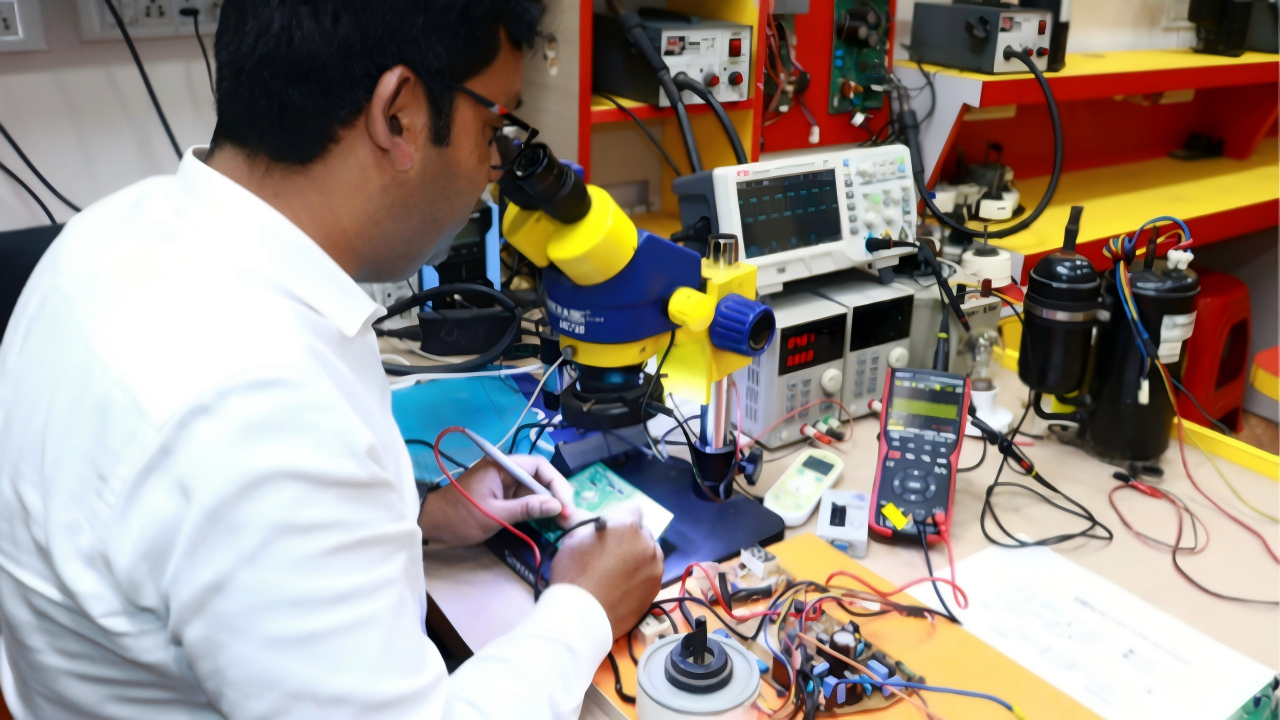
Before performing resistance and diode tests with a multimeter, you should disconnect the power supply first and isolate the solid state relay from the external circuit to ensure that the measurement is not affected by other components.
Although resistance and diode tests can help detect short circuits and similar faults, they cannot provide any indication of whether the SSR is functioning properly.
Resistance Test
- Test Steps
Set the multimeter to the resistance mode (Ω).
Connect the test probes to the terminals to be checked and record the multimeter reading.
Perform a check between the different connection combinations and compare the measurements to identify any obvious deviations.
- Interpretation of Results
If a path that should normally be open shows a value close to 0 Ω, a short circuit may be present.
If a path that is expected to conduct shows “OL” or an extremely high resistance, an open circuit may be present.
The internal structures of the various solid state relays differ from one another, and there is no fixed resistance value for each individual SSR. When measurements show significant deviations, you must make a specific assessment, taking into account the specific parameter table and the internal structure of the respective SSR.
Diode Test
- Test Steps
Set the multimeter to diode test mode.
Connect the multimeter’s test probes to the terminals to be checked.
Reverse the test probes and repeat the measurement.
Record measurement values in forward and reverse directions
- Interpretation of Results
If the measured values are extremely low in both directions or close to 0, this may indicate a short circuit in the line.
If “OL” is displayed in both directions during measurement, a possible open circuit may be present. However, this is a normal phenomenon with certain connection combinations.
If the measurement values are unstable or significantly deviate, there may be damage to the internal structure or another error requiring further verification.
This test cannot determine whether the relay is functioning properly. The internal structure and connections of the solid state relay significantly affect the measurement values. Therefore, when you are evaluating the test results, the technical specifications of the SSR must be taken into account.
Voltage and Signal Tests
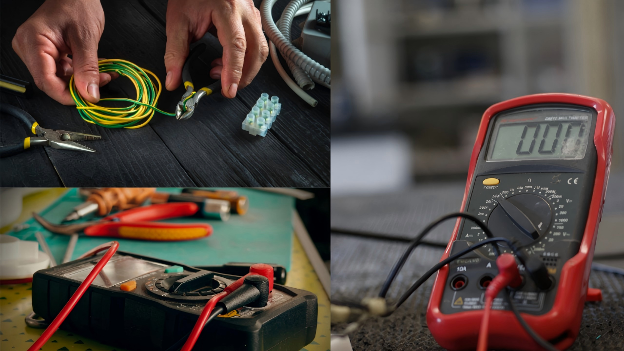
Voltage and signal tests are generally performed with the circuit energized. A multimeter is used to measure the input and output states of the solid state relay to verify that the control signal is correct and that the SSR performs the proper switching action in accordance with the input signal.
Input Voltage and Signal Test
- Test Steps
Connect the appropriate supply voltage to the SSR input.
Set the multimeter to the appropriate voltage measurement mode.
Measure the actual voltage of the SSR in both “ON” and “OFF” states of the test input signal.
When using pulse signals or control output signals, you need to verify that the signals are present and within the expected range.
- Interpretation of Results
Please note that the actual measured input voltage should fall within the input range specified for the solid state relay.
If no voltage is present at the input, it may be due to the control voltage, the control line, or the control device.
If the voltage is significantly below or above the specified range, the control signal may be abnormal.
If the signal is normal but the SSR does not respond accordingly, there may be a fault at the SSR output.
Output Voltage Test
- Test Steps
The two states “Input ON” and “Input OFF” must be measured.
Turn off the control signal, check the SSR’s output voltage, and measure the output voltage again after reconnecting the control signal.
- Interpretation of Results
If an output voltage is detected in the off state, do not immediately assume that the SSR is faulty. First, you should check the SSR’s specified off-state leakage current and determine whether the measured voltage can be attributed to leakage current and the characteristics of the load.
If the expected voltage is not measured at the outputs when the device is turned on, this may have various causes: check whether the input control signal is correct, whether a power supply is present on the output side, and whether the wiring, load, and SSR itself are in proper condition.
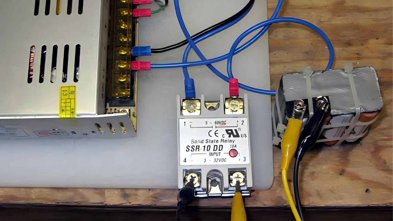
Leakage Current and On-State Voltage Drop Tests
Due to the internal semiconductor structure and working principle of the solid state relay, a certain leakage current exists in the off state, while a certain voltage drop occurs in the on state of the relay. By checking these two parameters, it is also possible to further assess whether the SSR’s operating condition meets the requirements.
Off-State Leakage Current Test
- Test Steps
By turning off the control signal, the SSR switches to the OFF state.
Connect an ammeter in series with the output circuit.
Apply a suitable test voltage to the SSR’s output side and measure the actual current in the output circuit when it is in the OFF state.
- Interpretation of Results
Compare the actual measured current with the leakage current specified in the SSR’s technical data. Under normal conditions, the measured values fall within the range indicated in the solid state relay’s technical data and are therefore normal.
If the measured values are significantly higher than the specifications, there may be a malfunction in the SSR’s output stage, a defect, or another issue within the circuit, and you need to require further investigation.
On-State Voltage Drop Test
- Test Steps
By applying an appropriate control signal at the input, the SSR switches to the ON state.
At the output, an appropriate test voltage and a suitable load are provided.
Set the multimeter to either DC or AC voltage mode.
Connect the multimeter probes to the two terminals of the SSR output and measure the voltage difference at the SSR.
- Interpretation of Results
When comparing the actual results with the solid state relay parameter specifications, a certain voltage drop is normally present across the SSR’s output terminals; this is a characteristic of the normal operation of semiconductor components.
If the voltage drop significantly exceeds the specifications, there may be a fault in the SSR’s internal output components, an output contact issue, or excessive load current; this must be further investigated.
Leakage current and on-state voltage drop also vary depending on the SSR’s rated voltage, load current, and internal design. Therefore, to evaluate test results, specific technical data provided by the respective solid state relay manufacturer must be used.
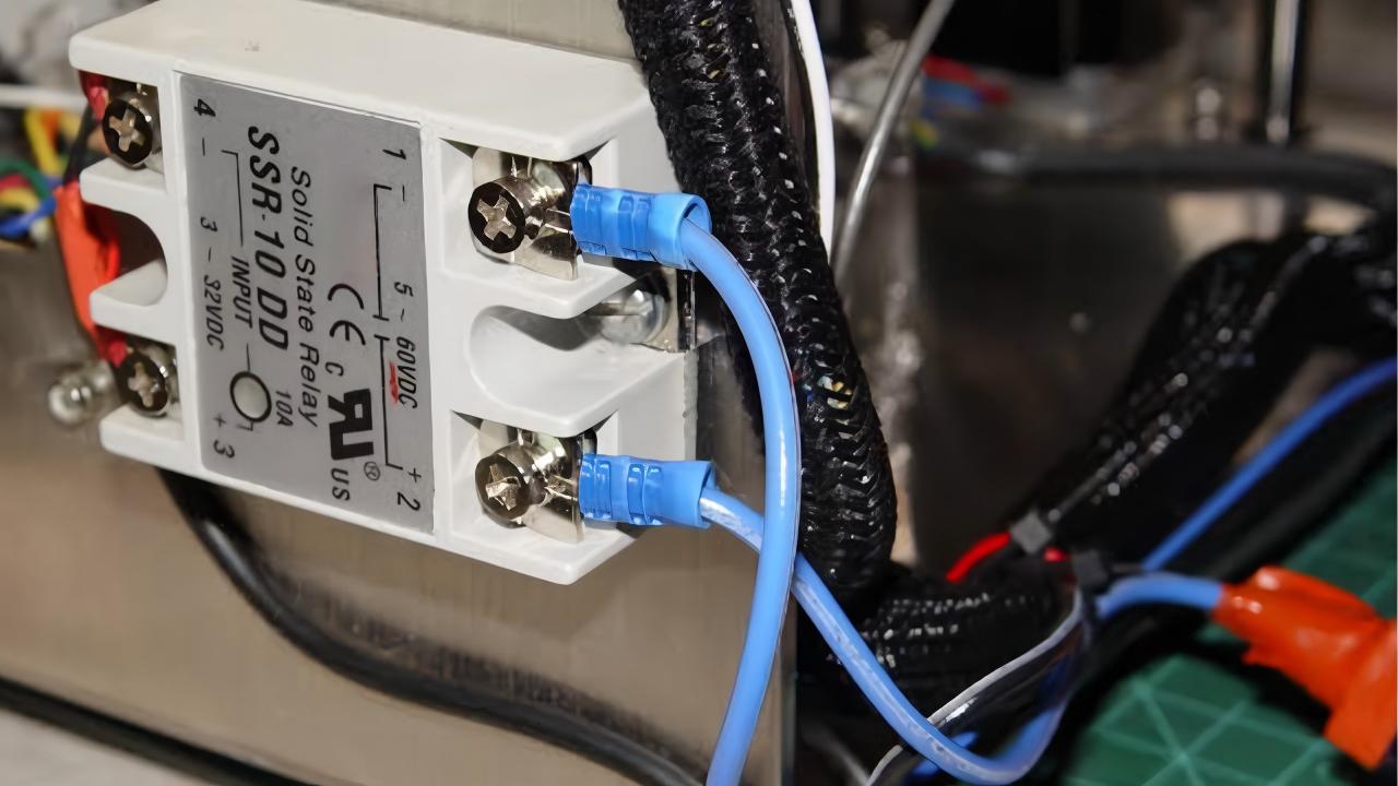
Dynamic Load Test
To verify whether the solid state relay can properly perform the switching operation under real conditions, a dynamic load test must be conducted. This test merely confirms that the device functions properly under current test conditions; however, it does not guarantee long-term reliability under all operating conditions.
- Test Steps
Connect the SSR with the appropriate control signal, power supply, and load correctly. Apply an appropriate control signal to the SSR to switch it into the ON state, and check the load, output current, proper functioning of the SSR, and look for any abnormal behavior. You can particularly observe the load switching, output current, voltage drop in the conducting state, the temperature, switching stability, and any other abnormal behavior.
Turn off the input signal, causing the SSR to switch to the OFF state. Monitor the load and simultaneously check whether the SSR is operating normally and if any abnormalities occur.
Turn the solid state relay ON and OFF repeatedly and check whether it functions properly.
Monitor data such as load current, SSR voltage drop, temperature, etc.
- Interpretation of Results
If the load does not function when turned on, it may be due to a disturbance in the control signal, a power supply failure at the output side, a wiring error, or a defect in the load itself.
If the load remains operational while in the off state, check for leakage current and whether the load may be particularly sensitive to it.
If the relay heats up too quickly or the temperature exceeds the permissible range significantly beyond the specifications, it may be due to excessive load current, excessive voltage drop across the SSR, or an unsuitable heat sink.
If the relay becomes unstable during repeated switching operations, this may be due to issues such as unstable control signals, an unsuitable load type, an incorrect SSR selection, or a defect in the SSR itself.
Common SSR Failure Modes & Possible Causes
Various malfunctions often occur during the testing process, why solid state relay not working? Below are common fault patterns and possible causes, designed to help you quickly troubleshooting solid state relay problems.
| Failure Mode | Typical Symptoms | Possible Causes |
| Shorted / Stuck ON | The signal is turned off, but the SSR remains in the conducting state. | Failure of the semiconductor output device due to overvoltage, overcurrent, severe overheating, or other electrical stress. |
| Open / Stuck OFF | The signal is correct, but the SSR cannot turn on the load. | Failure of the semiconductor output device, internal connection failure, or control circuit problems. |
| Excessive Leakage Current | The load shows abnormal behavior while the SSR is in the OFF state. | Off-state leakage current exceeds the specified limit, output-stage degradation, or internal damage. |
| Excessive On-State Voltage Drop | When the SSR is in the ON state, the voltage drop across the output terminals is unusually high. | Excessive load current, incorrect SSR selection, or degradation of the output device. |
| Overheating | Excessive SSR or heat sink temperature during operation. | Excessive load current, insufficient heat dissipation, incorrect selection of the heat sink, high ambient temperature, excessive voltage drop, etc. |
| Unstable Switching | Inconsistent switching behavior during repeated operations. | Unstable control signals, load mismatch, electrical interference, or incorrect SSR selection. |
A single reason is not sufficient to directly identify an solid state relay defect. It is advisable to compare all test results with the SSR’s technical specifications and inspect the relevant circuits and wiring to determine whether a defect exists.
FAQ
How Often Should a Solid State Relay be Tested?
There is no universal testing interval for solid state relays, the specific duration of each test cycle depends on the type of load, switching frequency, operating conditions, and the importance of the system.
Frequent inspections and tests are required for critical systems or applications under particularly harsh operating conditions; even in the event of SSR malfunctions, inspections and maintenance work must be carried out immediately.
What Causes a Solid State Relay to Fail Repeatedly?
After an solid state relay fails, the cause must first be determined; only then is it necessary to replace the SSR, it’s not sufficient to simply replace it. Repeated failures of SSRs may indicate that the root cause of the fault has not been addressed. Common causes of repeated solid state relay failures include excessive load current, high switching current peaks, voltage spikes or transient overvoltages, inadequate cooling, unsuitable SSR design, wiring or control issues, and mismatched load characteristics.
Therefore, after a malfunction occurs, you should carefully investigate the root cause and then take appropriate measures.
What is the Difference Between Testing an SSR and a Mechanical Relay?
The main difference between testing solid state relays and mechanical relays lies in the fact that, due to their different operating mechanisms, the testing procedures and parameters used for evaluation also differ.
Compared to SSRs, testing mechanical relays is often more intuitive, you can primarily check the coil condition, contact conductivity, and contact resistance.
When Should a Solid State Relay be Replaced?
If the solid state relay shows clear physical damage such as burns, melting marks, or cracks, deviates significantly from the standard electrical parameters, or is overheating, you should replaced it immediately to prevent the defect from further affecting the system operation or causing other electrical issues.
Before replacing, you can check the surrounding circuits, load, wiring, control signals, and cooling to ensure that the SSR is indeed faulty, and rule out other external causes for the solid state relay damage.
Why does a New Solid State Relay Burn Out Almost Immediately After Installation?
This could be due to improper installation of the new solid state relay, load mismatch, or excessively high current or voltage values.
Common causes of solid state relay failure include wiring errors, excessive load currents, unsuitable load voltages, high inrush current, transient voltages, incorrect SSR selection, and inadequate cooling.
Can I Test a Three-Phase Solid State Relay Using the Same Single-Phase Procedure?
Although the fundamental principles of both are similar, the testing procedures for single-phase SSRs cannot be directly applied. In three-phase SSRs, all phases must be tested individually; data and switching states should be evaluated separately under the same test conditions, and the three-phase circuit should be considered as a whole.
What Resistance Should a Solid State Relay Have?
There is no fixed resistance value suitable for all solid state relays; the specific value depends on the internal semiconductor structure, input and output configuration, as well as the connections to be tested. Therefore, you can’t determine whether the SSR is functioning properly solely by measuring its resistance value with a multimeter.
Final Thoughts
If your solid state relay no longer meets the requirements of your application, you might want to replace it. LCTC offers a wide range of SSR types for various industrial applications, covering numerous product series.
We warmly invite you to explore our SSR product range. Should you need assistance, feel free to contact us at any time. LCTC offers support in product selection, OEM/ODM services, and technical support.