
Why We Choose LCTC 3-32VDC Control Solid State Relay
- Certified with CE
- Rapid response for increased efficiency
- No mechanical wear; components are resistant to damage
- Compatible with 3V, 5V, 12V, 24V, and 32V DC inputs
3-32VDC Solid State Relay Manufacturer from China
As a professional manufacturer and supplier of electrical components, LCTC is dedicated to providing reliable switching and control solutions for a wide range of applications in industrial equipment.
The 3 to 32 VDC solid-state relay is designed to operate under a wide range of input conditions, enabling stable switching regardless of whether the control system operates at 3V, 5V, 12V, 24V, and 32V. Thanks to its high-speed response, ultra-long lifespan, and stable performance, it is widely used in various control systems, such as sensors and PLC.
If you are interested in our products, feel free to send us a query or contact us directly through the online chat function located in the bottom right corner; we will respond as quickly as possible.
Product By Features
The 3-32VDC solid-state relay is specifically designed for DC solid state relay , including DC to DC or DC to AC; all products listed below feature a DC input type.
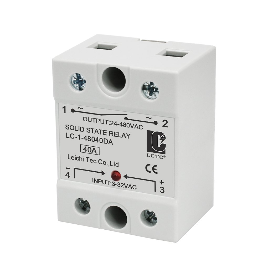
Specifically designed for controlling single phase loads, available in two configurations, zero-crossing and random activation, and supports custom solutions.
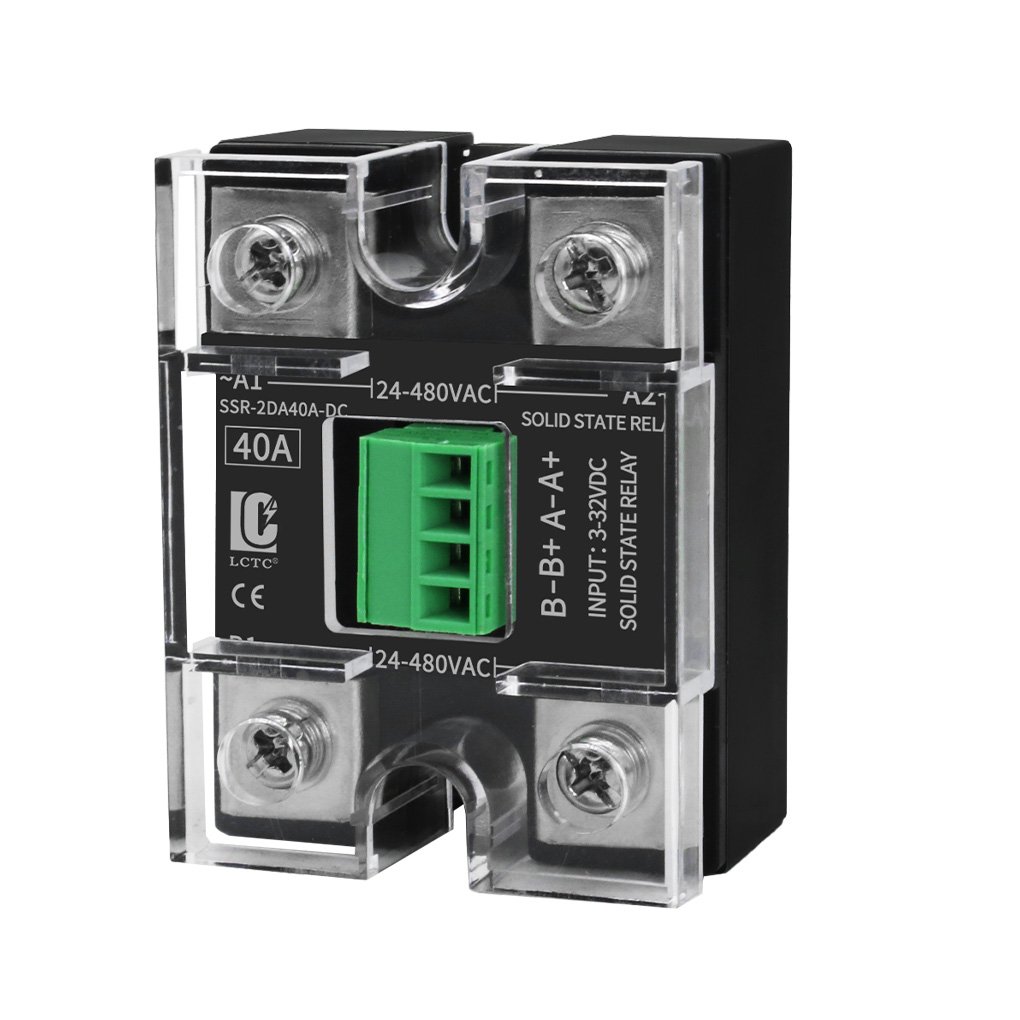
Good choice for double phase power distribution, with a compact design and the ability to simultaneously control two independent loads.
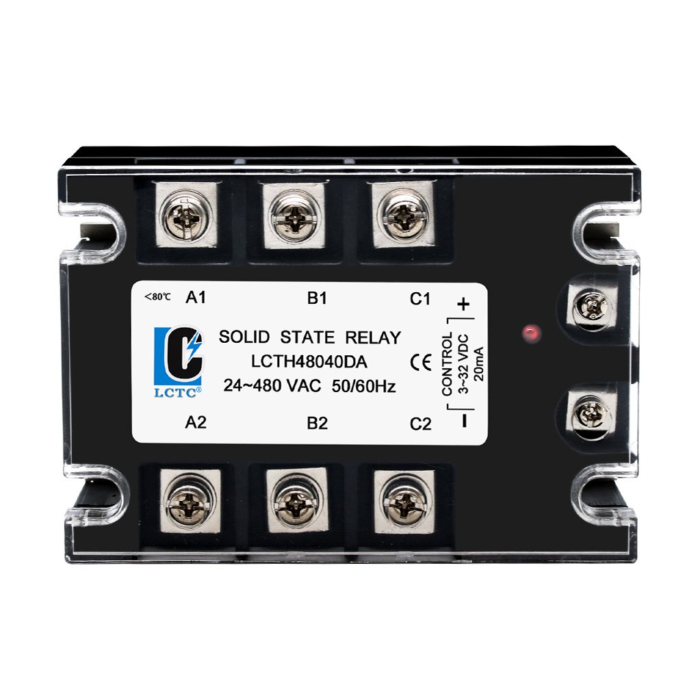
Specifically designed for three phase power applications, it offers powerful and highly synchronized switching capabilities.
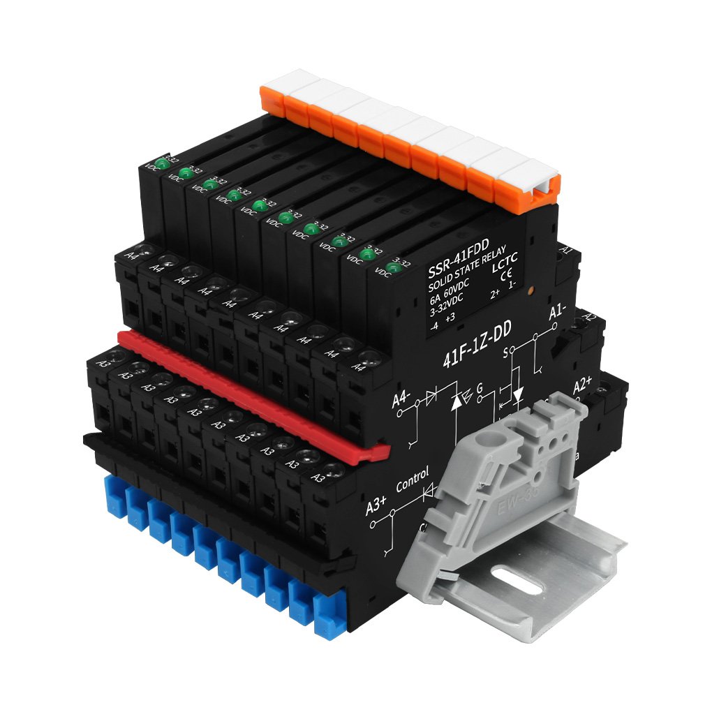
The modular design enables compact control, facilitates easy integration and installation, and ensures efficient use of space.
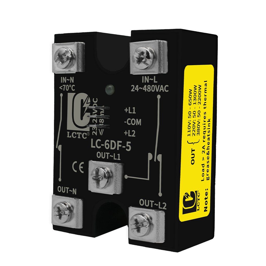
Specifically designed for controlling the motor forward and backward, it provides options for safe and quick changes in rotation direction.
Feature of 3-32VDC Solid State Relay
The 3-32 VDC solid-state relay, used in various industries, has the following characteristics.

Wide input voltage SSR control eliminates the need for numerous model variations, ensures more stable switching, and simplifies electrical design and engineering complexity.

Its wide-range input is compatible with both legacy systems and PLC-based automation platforms, making it an ideal solution for equipment upgrading and modernization.

Wide-range input control can be used directly, eliminating the need for redundant converters; with fewer components, potential risks are also reduced.

With a maximum input control of 32 VDC, it protects sensitive equipment from voltage spikes, electrical noise, and similar threats, providing enhanced safety and protection for your devices.
Wide Voltage Control Range with Highly Compatible
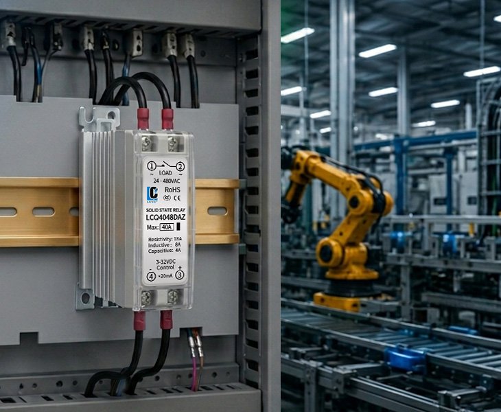
The LCTC 3-32VDC solid-state relay is specifically designed to accept a wide range of DC control signals; it supports various voltages, including 3V, 5V, 12V, 24V and 32V, thereby effectively minimizing the risk of selection errors. Its exceptional performance and wide compatibility enable flexible application in PLCs, sensors, and various industrial automation devices.
3-32VDC Solid State Relay Download
Wide Input 3-32VDC Solid State Relay Wholesale
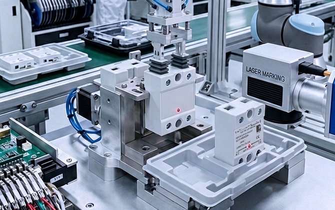

Leveraging nearly a decade of experience in manufacturing and supply within the electrical components industry, we are dedicated to providing professional switch control solutions for various industrial equipment sectors. From R&D to production, each stage is subject to a rigorous Japanese-style quality control system designed to ensure product reliability. We also offer OEM/ODM services, providing customized and tailored solutions to meet various requirements.
We remain committed to our singular mission: providing you with exceptional-quality, high-efficiency 3 to 32 VDC solid-state relays; serving as a reliable SSR factory and becoming your trusted partner.
Application of 3-32VDC Solid State Relay
Due to their wide input range of 3 to 32 VDC, fast response time, and photoelectric isolation characteristics, solid-state relays are widely used in various industries and types of equipment.

The LCTC 3-32VDC solid state relay is compatible with a wide range of DC input control signals, eliminating the need to switch to a different solid-state relay for different voltages. It is compatible with PLC control cabinets, automated production lines, automated assembly lines, and similar systems.

The LCTC 3-32VDC solid-state relay is capable of high-frequency switching; by eliminating mechanical contacts, it prevents wear and tear. When used in packaging equipment, such as automatic packaging machines, labelers, and sealers, it enables frequent start-stop operations for conveyor belts, solenoid valves, and similar components.

The LCTC 3-32VDC solid-state relay, with its photoelectric isolation and fast response capabilities, is commonly used in solar energy storage systems, such as battery energy storage systems, solar controllers, and energy management systems.

The LCTC 3–32 VDC solid-state relay offers a wide output voltage range, allowing flexible adaptation to various control systems. It is ideal for managing control signals of different voltages within water treatment equipment, such as treatment systems, filtration systems, and similar applications.

Testimonials
In my automated packaging machine, I have implemented a solid-state relay from 3 to 32 VDC. Now I can use the exact same relay model in both my 5 V control panel and my 24 V PLC system. I’ve been using this configuration for eight months now; the equipment has operated with great stability, and so far, no failures of any kind have occurred.
——Technical Engineer, Korea
I installed the LCTC 3-32VDC solid-state relay into a solar energy storage system; the installation was quick and the response immediate. It is compatible with both 12 V and 24 V control signals—which is extremely convenient, and has greatly simplified the system design process across multiple product lines.
——Procurement Lead, Singapore
Yes, of course. A 24 V PLC can directly operate a solid-state relay from 3 to 32 VDC This falls within the wide input range; as long as the control voltage remains within this specific range, the device is fully capable of accepting standard industrial 24 VDC signals.
Generally, it ranges from 0.1 milliseconds to several milliseconds; the specific speed depends on the model and load conditions.
Solid State Relay Working Principle
A solid state relay is an electronic switch controlled by semiconductor components; compared to traditional mechanical relays, it lacks mechanical contacts and therefore avoids contact wear.
How Does a Solid State Relay Work
When you need to control the voltage applied to the input terminal, a small current activates the internal Light Emitting Diode (LED), allowing devices such as PLCs and sensors to directly operate the unit.
The light emitted by the LED is received by an internal photosensitive element, enabling the transmission of control signals even in the absence of a direct electrical connection between the input and output; this mechanism is known as optical coupling.
In this configuration, the charging and discharging are controlled by semiconductor components located at the output terminal. Different types of relays use various devices to regulate current flow; common options include MOSFETs, transistors, triacs, and SCRs.
When the control signal is present, the output stage conducts, current flows through the load, and the device operates normally. When the control signal is removed, the output stage shuts off, current ceases to flow, and the load is disconnected.
In summary, the operating principle of a solid-state relay involves converting an electrical control signal into an optical signal, which subsequently activates a semiconductor switching element to achieve control over the load.
How to Wire A Solid State Relay
As an electronic switching component, it uses semiconductor technology—instead of mechanical contacts—for its control; proper wiring ensures the solid-state relay operates safely, stably, and reliably.
Step 1: Identify the SSR Terminals.
Before you proceed with wiring, it is essential to identify the terminals. Typically, a solid-state relay consists of two sections: an input side and an output side. The input side receives control signals from automation devices—such as PLCs or controllers—while the output side connects to the load and power supply.
Step 2: Connect the Control Input Terminal.
Connect the control device to the SSR’s input terminals, ensuring that the input voltage of the connected device falls within the specified range. For a DC input, connect the positive signal terminal to the “+” terminal and the negative terminal to the “-” terminal. Typically, the DC input range is 3 to 32 VDC, allowing connection to control signals such as 5 V, 12 V, or 24 V.
Step 3: Connect the Power Circuit.
The SSR output terminals are connected in series with the load. The typical connection path follows this sequence: power supply, SSR output, load, and return line. When a control signal is applied, the internal electronic switch activates, allowing current to flow through the load.
Step 4: Verify Load Compatibility
Before you connect the power supply, verify that the load voltage matches the relay’s rated output, that the load current falls within the SSR’s rated range, and that the correct type of SSR has been selected. Generally, four types are available: AC controlled by DC, DC controlled by DC, DC controlled by AC, and AC controlled by AC.
Step 5: Consider Heat Dissipation.
In high-current applications, SSRs generate a significant amount of heat during operation. If this heat is not dissipated properly, it can easily compromise the operational performance and lifespan of the SSR. Therefore, it is necessary to consider installing an appropriate heat sink to ensure normal operation.
Step 6: Test the System
Once you have completed all the wiring, verify that all connection points are properly wired and apply control signals to check whether the load turns on and off normally.
In summary, wiring an SSR is quite straightforward; however, it is essential to follow standard wiring procedures and ensure that parameters such as input current and load remain within the SSR’s nominal specifications. Only in this way can the SSR be guaranteed to operate efficiently across a wide range of applications.